|
|
|
PDF NGTG15N60S1EG Data sheet ( Hoja de datos )
| Número de pieza | NGTG15N60S1EG | |
| Descripción | IGBT | |
| Fabricantes | ON Semiconductor | |
| Logotipo | ||
Hay una vista previa y un enlace de descarga de NGTG15N60S1EG (archivo pdf) en la parte inferior de esta página. Total 9 Páginas | ||
|
No Preview Available !
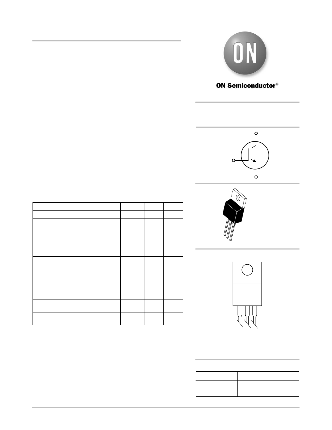
NGTG15N60S1EG
IGBT - Short-Circuit Rated
This Insulated Gate Bipolar Transistor (IGBT) features a robust and
cost effective Non−Punch Through (NPT) Trench construction, and
provides superior performance in demanding switching applications.
Offering both low on state voltage and minimal switching loss, the
IGBT is well suited for motor drive control and other hard switching
applications.
Features
• Low Saturation Voltage Resulting in Low Conduction Loss
• Low Switching Loss in Higher Frequency Applications
• 5 ms Short Circuit Capability
• Excellent Current versus Package Size Performance Density
• This is a Pb−Free Device
Typical Applications
• White Goods Appliance Motor Control
• General Purpose Inverter
• AC and DC Motor Control
ABSOLUTE MAXIMUM RATINGS
Rating
Symbol Value Unit
Collector−emitter voltage
Collector current
@ TC = 25°C
@ TC = 100°C
Pulsed collector current, Tpulse limited by
TJmax
Gate−emitter voltage
Power dissipation
@ TC = 25°C
@ TC = 100°C
Short circuit withstand time
VGE = 15 V, VCE = 400 V, TJ v +150°C
Operating junction temperature range
VCES
IC
ICM
VGE
PD
tSC
TJ
600
30
15
120
$20
117
47
5
−55 to
+150
V
Ahttp://www.DataSheet4U.net/
A
V
W
ms
°C
Storage temperature range
Tstg
−55 to
°C
+150
Lead temperature for soldering, 1/8” from
TSLD
260
°C
case for 5 seconds
Stresses exceeding Maximum Ratings may damage the device. Maximum
Ratings are stress ratings only. Functional operation above the Recommended
Operating Conditions is not implied. Extended exposure to stresses above the
Recommended Operating Conditions may affect device reliability.
http://onsemi.com
15 A, 600 V
VCEsat = 1.5 V
C
G
E
C
G CE
TO−220
CASE 221A
STYLE 4
MARKING DIAGRAM
G15N60S1G
AYWW
A = Assembly Location
Y = Year
WW = Work Week
G = Pb−Free Package
ORDERING INFORMATION
Device
Package
Shipping
NGTG15N60S1EG TO−220 50 Units / Rail
(Pb−Free)
© Semiconductor Components Industries, LLC, 2012
August, 2012 − Rev. 2
1
Publication Order Number:
NGTG15N60S1E/D
datasheet pdf - http://www.DataSheet4U.net/
1 page 
NGTG15N60S1EG
TYPICAL CHARACTERISTICS
1000
tf
100
td(off)
td(on)
tr
10 VCE = 400 V
VGE = 15 V
IC = 15 A
TJ = 150°C
1
5 15 25 35 45 55 65 75 85
RG, GATE RESISTOR (W)
Figure 13. Switching Time vs. RG
1.2
VGE = 15 V
IC = 15 A
0.9 RG = 22 W
TJ = 150°C
0.6
Eon
Eoff
0.3
0 175 225 275 325 375 425 475 525 575
VCE, COLLECTOR−EMITTER VOLTAGE (V)
Figure 14. Switching Loss vs. VCE
1000
tf
100 td_off
td_on
tr
10 VGE = 15 V
IC = 15 A
RG = 22 W
TJ = 150°C
1
175 225 275 325 375 425 475 525 575
VCE, COLLECTOR−EMITTER VOLTAGE (V)
Figure 15. Switching Time vs. VCE
1000
100
1 ms
100 ms
10
dc operation
50 ms
1
0.1http://www.DataSheet4U.net/
0.01
1
Single Nonrepetitive
Pulse TC = 25°C
Curves must be derated
linearly with increase
in temperature
10
100
VCE, COLLECTOR−EMITTER VOLTAGE (V)
Figure 16. Safe Operating Area
1000
1000
100
10
1
0.1
0.01 VGE = 15 V, TC = 125°C
1 10
100
1000
VCE, COLLECTOR−EMITTER VOLTAGE (V)
Figure 17. Reverse Bias Safe Operating Area
http://onsemi.com
5
datasheet pdf - http://www.DataSheet4U.net/
5 Page | ||
| Páginas | Total 9 Páginas | |
| PDF Descargar | [ Datasheet NGTG15N60S1EG.PDF ] | |
Hoja de datos destacado
| Número de pieza | Descripción | Fabricantes |
| NGTG15N60S1EG | IGBT | ON Semiconductor |
| Número de pieza | Descripción | Fabricantes |
| SLA6805M | High Voltage 3 phase Motor Driver IC. |
Sanken |
| SDC1742 | 12- and 14-Bit Hybrid Synchro / Resolver-to-Digital Converters. |
Analog Devices |
|
DataSheet.es es una pagina web que funciona como un repositorio de manuales o hoja de datos de muchos de los productos más populares, |
| DataSheet.es | 2020 | Privacy Policy | Contacto | Buscar |