|
|
|
PDF SF2149A Data sheet ( Hoja de datos )
| Número de pieza | SF2149A | |
| Descripción | SAW Filter | |
| Fabricantes | RF Monolithics | |
| Logotipo | ||
Hay una vista previa y un enlace de descarga de SF2149A (archivo pdf) en la parte inferior de esta página. Total 4 Páginas | ||
|
No Preview Available !
Preliminary
• TD-SCDMA SAW Filter, 46.08 MHz, 5 MHz BW
• Low Insertion Loss
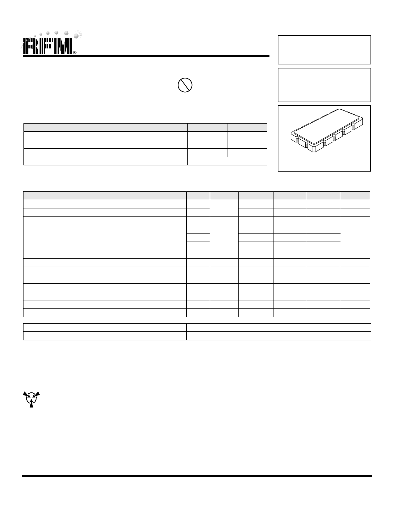
• 13.3 x 6.5 x 1.9 mm Surface-mount Case
• Complies with Directive 2002/95/EC (RoHS)
Pb
SF2149A
46.08 MHz
SAW Filter
Absolute Maximum Ratings
Rating
Maximum Incident Power in Passband
Max. DC voltage between any 2 terminals
Storage Temperature Range
Suitable for lead-free soldering - Max. Soldering Profile
Value
+10
Units
dBm
30 VDC
-40 to +85
°C
260°C for 10 s
SM13365-12
Electrical Characteristics
Characteristic
Nominal Center Frequency
Passband bandwidth
Insertion Loss
Relative Attenuation to IL @
out of pass band (Rejection)
Amplitude ripple (p-p)
Amplitude ripple (p-p) @ 25°C
Group delay ripple (p-p)
1 dB compression Point
Input IP3
Operating Temperature
Terminating impedance
43.58 ... 48.58 MHz
30 ... 41.98 MHz
61.44 MHz
50.18 ... 76.8 MHz
<30 MHz &>76.8 MHz
43.58 ... 48.58 MHz
43.58 ... 48.58 MHz
43.58 ... 48.58 MHz
43.58 ... 48.58 MHz
Sym
fN
BW
IL
Notes
1
1, 2,3
www.DataSheet.net/
Min
5
20
40
15
40
12
35
-40
Typ
46.08
8
25
45
25
45
0.6
0.8
100
15
40
50
Max
10
1.0
120
+85
Case Style
Lid Symbolization (YY = year, WW = week, S=shift) See note 4
SM13365-12 13.3 x 6.5 mm Nominal Footprint
RFM SF2149A // YYWWS
Units
MHz
MHz
dB
dB
dB
ns
dBm
dBm
°C
Ohm
CAUTION: Electrostatic Sensitive Device. Observe precautions for handling.
Notes:
1. Unless noted otherwise, all specifications apply over the operating tem-
perature range with filter soldered to the specified demonstration board
with impedance matching to 50 Ω and measured with 50 Ω network ana-
lyzer.
2. Unless noted otherwise, all frequency specifications are referenced to the
nominal center frequency, fc.
3. Rejection is measured as attenuation below the minimum IL point in the
passband. Rejection in final user application is dependent on PCB layout
and external impedance matching design. See Application Note No. 42
for details.
4. Part to part absolute delay measurement records the absolute delay
mean across 1 dB passband.
5. "LRIP" or "L" after the part number indicates "low rate initial production"
and "ENG" or "E" indicates "engineering prototypes.”
6. The design, manufacturing process, and specifications of this filter are
subject to change.
7. Either Port 1 or Port 2 may be used for either input or output in the design.
However, impedances and impedance matching may vary between Port 1
and Port 2, so that the filter must always be installed in one direction per
the circuit design.
8. US and international patents may apply.
www.RFM.com E-mail: [email protected]
©2008 by RF Monolithics, Inc.
Page 1 of 4
SF2149A - 1/11/11
Datasheet pdf - http://www.DataSheet4U.co.kr/
1 page | ||
| Páginas | Total 4 Páginas | |
| PDF Descargar | [ Datasheet SF2149A.PDF ] | |
Hoja de datos destacado
| Número de pieza | Descripción | Fabricantes |
| SF2149A | SAW Filter | RF Monolithics |
| Número de pieza | Descripción | Fabricantes |
| SLA6805M | High Voltage 3 phase Motor Driver IC. |
Sanken |
| SDC1742 | 12- and 14-Bit Hybrid Synchro / Resolver-to-Digital Converters. |
Analog Devices |
|
DataSheet.es es una pagina web que funciona como un repositorio de manuales o hoja de datos de muchos de los productos más populares, |
| DataSheet.es | 2020 | Privacy Policy | Contacto | Buscar |