|
|
|
PDF HFB60HF20C Data sheet ( Hoja de datos )
| Número de pieza | HFB60HF20C | |
| Descripción | Soft Recovery Diode | |
| Fabricantes | International Rectifier | |
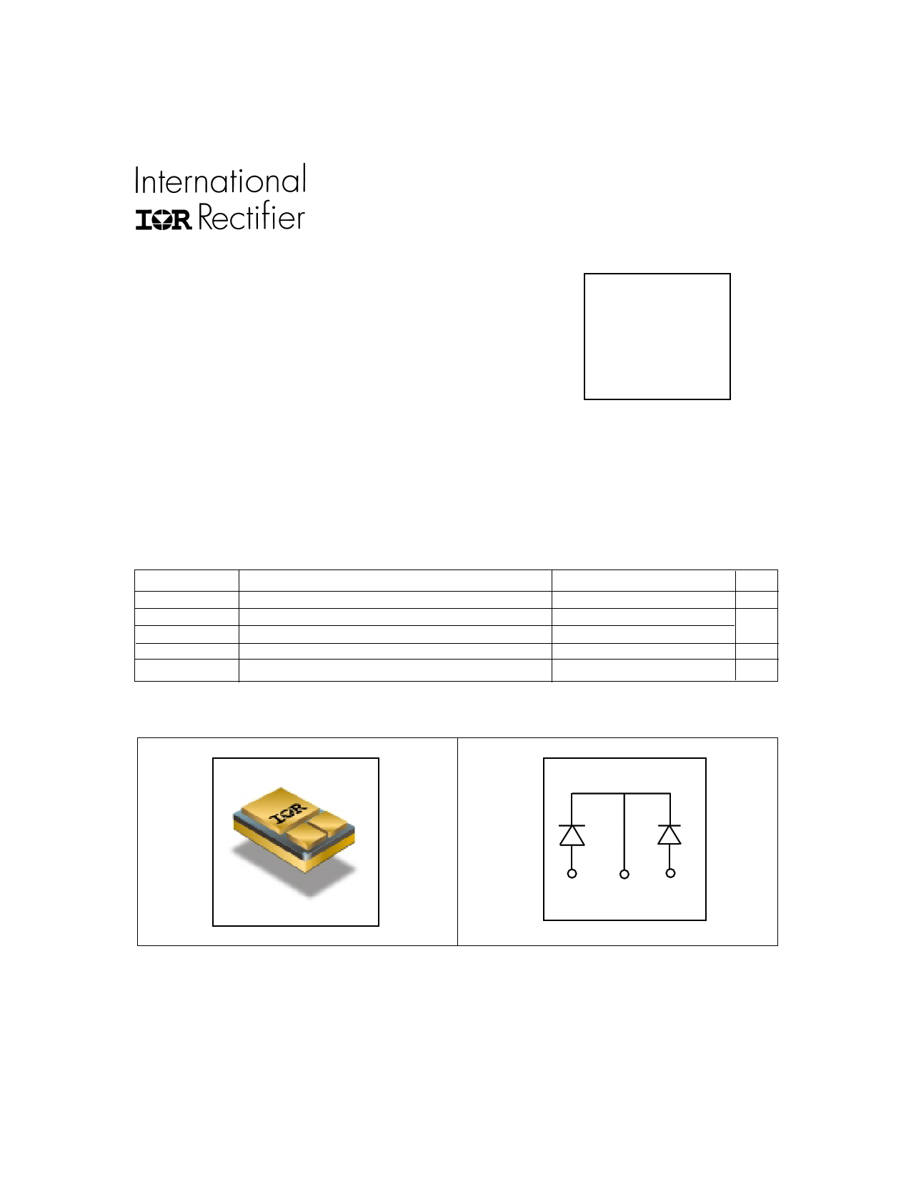
| Logotipo | ||
Hay una vista previa y un enlace de descarga de HFB60HF20C (archivo pdf) en la parte inferior de esta página. Total 5 Páginas | ||
|
No Preview Available !
FRED
Features
• Reduced RFI and EMI
• Reduced Snubbing
• Extensive Characterization of Recovery Parameters
• Hermetic
• Surface Mount
PD - 94228A
HFB60HF20C
Ultrafast, Soft Recovery Diode
VR = 200V
IF(AV) = 60A
trr = 35ns
Description
These Ultrafast, soft recovery diodes are optimized to reduce losses and EMI/RFI in high frequency power
conditioning systems. An extensive characterization of the recovery behavior for different values of current,
temperature and di/dt simplifies the calculations of losses in the operating conditions. The softness of the recovery
eliminates the need for a snubber in most applications. These devices are ideally suited for power converters, motors
drives and other applications where switching losses are significant portion of the total losses.
Absolute Maximum Ratings
VR
IF(AV)
IFSM
PD @ TC = 25°C
TJ, TSTG
Parameter
Cathode to Anode Voltage ( Per Leg )
Continuous Forward Current, Q TC = 50°C
Single Pulse Forward Current, R TC = 25°C ( Per Leg )
Maximum Power Dissipation
Operating Junction and Storage Temperature Range
Note: Q D.C. = 50% rect. wave
R 1/2 sine wave, 60 Hz , P.W. = 8.33 ms
Max.
200
60
300
46
-55 to +150
Units
V
A
W
°C
CASE STYLE
(ISOLATED BASE)
SMD-1
ANODE COMMON ANODE
CATHODE
www.irf.com
1
7/9/01
www.DataSheet.in
1 page 
HFB60HF20C
REVERSE RECOVERY CIRCUIT
VR = 200V
L = 70µH
0.01 Ω
D .U .T.
dif/dt
ADJUST G
D
IRFP250
S
IF
0
3
trr
ta
tb
2
I RRM
4
Q rr
0.5 I RRM
di(rec)M /dt
5
1 dif /dt
1. dif/dt - Rate of change of current
through zero crossing
2. IRRM - Peak reverse recovery current
3. trr - Reverse recovery time measured
from zero crossing point of negative
going IF to point where a line passing
through 0.75 IRRM and 0.50 IRRM
extrapolated to zero current
0.75 IRRM
4. Qrr - Area under curve defined by trr
and IRRM
trr X IRRM
Qrr =
2
5. di(rec)M/dt - Peak rate of change of
current during tb portion of trr
Fig. 9 - Reverse Recovery Parameter Test Circuit Fig. 10 - Reverse Recovery Waveform and Definitions
Case Outline and Dimensions — SMD-1
1 = COMMON CATHODE
2 = ANODE 1
3 = ANODE 2
IR WORLD HEADQUARTERS: 233 Kansas St., El Segundo, California 90245, USA Tel: (310) 252-7105
TAC Fax: (310) 252-7903
Visit us at www.irf.com for sales contact information.
Data and specifications subject to change without notice. 07/01
www.irf.com
5
www.DataSheet.in
5 Page | ||
| Páginas | Total 5 Páginas | |
| PDF Descargar | [ Datasheet HFB60HF20C.PDF ] | |
Hoja de datos destacado
| Número de pieza | Descripción | Fabricantes |
| HFB60HF20 | Soft Recovery Diode | International Rectifier |
| HFB60HF20C | Soft Recovery Diode | International Rectifier |
| Número de pieza | Descripción | Fabricantes |
| SLA6805M | High Voltage 3 phase Motor Driver IC. |
Sanken |
| SDC1742 | 12- and 14-Bit Hybrid Synchro / Resolver-to-Digital Converters. |
Analog Devices |
|
DataSheet.es es una pagina web que funciona como un repositorio de manuales o hoja de datos de muchos de los productos más populares, |
| DataSheet.es | 2020 | Privacy Policy | Contacto | Buscar |