|
|
|
PDF EMIF02-MIC07F3 Data sheet ( Hoja de datos )
| Número de pieza | EMIF02-MIC07F3 | |
| Descripción | EMI filter and ESD protection | |
| Fabricantes | ST Microelectronics | |
| Logotipo | ||
Hay una vista previa y un enlace de descarga de EMIF02-MIC07F3 (archivo pdf) en la parte inferior de esta página. Total 7 Páginas | ||
|
No Preview Available !
www.DataSheet4U.com
EMIF02-MIC07F3
EMI filter and ESD protection
Features
■ EMI symmetrical (I/O) low-pass filter
■ High efficiency in EMI/ESD protection
■ Lead-free package
■ Very thin package
■ High reliability offered by monolithic integration
■ High reduction of parasitic elements through
integration and wafer level packaging
Complies with the following standards
■ IEC 61000-4-2 level 4
(on external pins B1 and C1)
– + 15 kV (air discharge)
– + 8 kV (contact discharge)
■ IEC 61000-4-2 level 1
(on external pins)
– + 2 kV (air discharge)
– + 2 kV (contact discharge)
Applications
Where EMI filtering in ESD sensitive equipment is
required:
■ Mobile phones and communication systems
■ Computers, printers and MCU Boards
Description
The EMIF02-MIC07F3 chip is a highly integrated
audio filter device designed to suppress EMI/RFI
noise in all systems subjected to electromagnetic
interference.
This filter includes ESD protection circuitry, which
prevents damage to the protected device when
subjected to ESD surges up to 15 kV.
TM: IPAD is a trademark of STMicroelectronics.
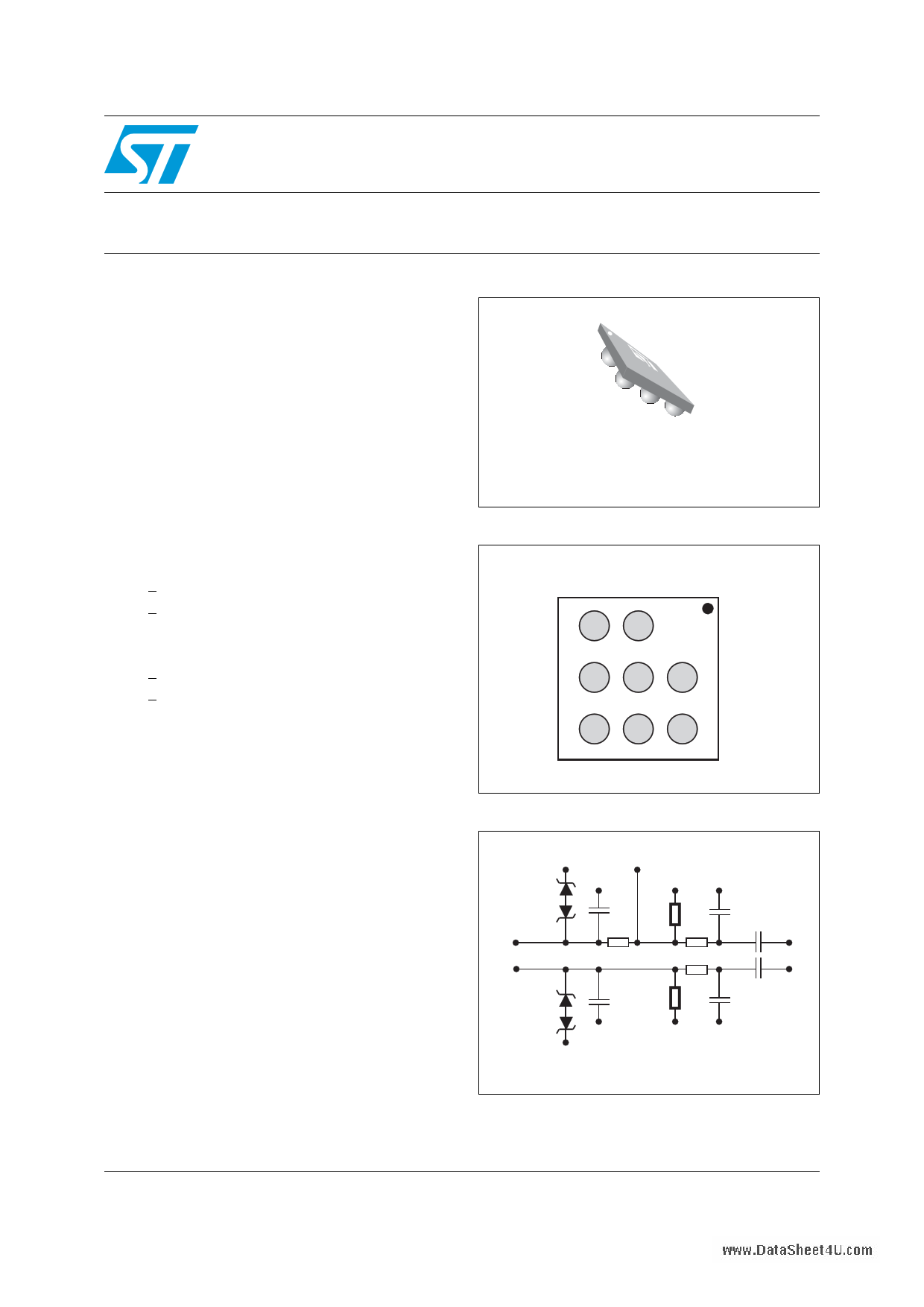
Lead-free Flip-Chip package
(8 bumps)
Figure 1. Pin configuration (bump side)
321
MIC
Bias
Acc_Det
A
Op Gnd Mic2p
B
On Gnd Mic2n
C
Figure 2. Schematic
GND
Acc_Det
GND
C11
A2
Mic Bias
A3
R11
GND
C21
B1
Mic2p
Mic2n
C1
R31 R21 C31 B3
to ASIC
C32
R22 C3
C12 R12 C22
GND
GND
GND
GND
B2 and C2 are ground bumps and must be connected together
March 2010
Doc ID 17052 Rev 1
1/7
www.st.com
7
1 page 
EMIF02-MIC07F3
www.DataSheet4U.com
Ordering information
Figure 12. Footprint recommendations Figure 13. Marking
Copper pad Diameter:
220µm recommended
260µm maximum
Solder mask opening:
300µm minimum
Dot, ST logo
xx = marking
z = manufacturing location
yww = datecode
(y = year
ww = week)
Solder stencil opening :
220µm recommended
E
xxz
y ww
Figure 14. Flip-Chip tape and reel specification
0.20 ± 0.02
2.0 ± 0.05 4.0 ± 0.1
Ø 1.55 ± 0.05
0.69 ± 0.05
All dimensions in mm
1.29
User direction of unreeling
4 Ordering information
Note:
Table 3. Ordering information
Order code
Marking
Package
EMIF02-MIC07F3
JE
Flip Chip
Weight
1.8 mg
Base qty
5000
Delivery mode
Tape and reel 7”
More information is available in the application notes
AN2348: “Flip Chip: Package description and recommendations for use”
AN1751: "EMI Filters: Recommendations and measurements"
Doc ID 17052 Rev 1
5/7
5 Page | ||
| Páginas | Total 7 Páginas | |
| PDF Descargar | [ Datasheet EMIF02-MIC07F3.PDF ] | |
Hoja de datos destacado
| Número de pieza | Descripción | Fabricantes |
| EMIF02-MIC07F3 | EMI filter and ESD protection | ST Microelectronics |
| Número de pieza | Descripción | Fabricantes |
| SLA6805M | High Voltage 3 phase Motor Driver IC. |
Sanken |
| SDC1742 | 12- and 14-Bit Hybrid Synchro / Resolver-to-Digital Converters. |
Analog Devices |
|
DataSheet.es es una pagina web que funciona como un repositorio de manuales o hoja de datos de muchos de los productos más populares, |
| DataSheet.es | 2020 | Privacy Policy | Contacto | Buscar |