|
|
|
PDF NJW4351 Data sheet ( Hoja de datos )
| Número de pieza | NJW4351 | |
| Descripción | Unipolar Stepper Motor Driver | |
| Fabricantes | NJR | |
| Logotipo | ||
Hay una vista previa y un enlace de descarga de NJW4351 (archivo pdf) en la parte inferior de esta página. Total 18 Páginas | ||
|
No Preview Available !
NJW4351www.DataSheet4U.com
Unipolar Stepper Motor Driver
GENERAL DESCRIPTION
The NJW4351 is a high efficiency DMOS unipolar stepper
motor driver IC. Compared to previous devices, it is more suitable
for low voltage operation, capable of handling 5.0V, 3.3V and the
like logic circuits. Drive Stage consists of DMOS which produces
high efficiency and low heat generation motor drive circuit.
The motor can be controlled by the STEP and DIR system.
Further more, to improve controllability of system, MO, ENABLE,
RESET and PD function are included, various applications are
possible.
FEATURES
• Supply Voltage
VDD=2.7 to 5.5V
VMM= to 55V
• Output Current
Io=1.5A peak at VDD=5V
• Low Quiescent Current IDD=500µA typ.
• STEP&DIR Input Operation (Internal Translator)
• HALF/FULL Mode Generation
• TTL compatible Input With Schmitt-Comparator
• ENABLE Function
• RESET Function
• MO (Motor Origin Monitor) -Position-indication Output
• PD (Standby) Function
• Under Voltage Lock Out
• Thermal Shutdown Circuit
• Alarm Output Function (As the protection circuit operates)
• BCD Technology
• Package Outline
SSOP20-C3, DIP16
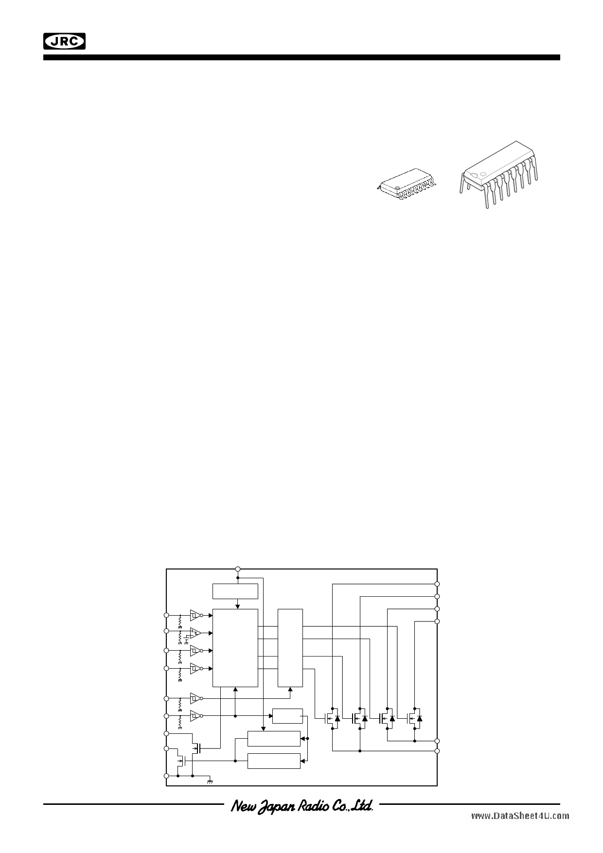
BLOCK DIAGRAM
HSM
STEP
DIR
RESET
NJW4351
VDD
POWER ON
RESET
TRANSLATOR
GATE
DRIVE
PACKAGE OUTLINE
NJW4351VC3
NJW4351D
OUT2B
OUT2A
OUT1B
OUT1A
ENABLE
PD
MO
ALARM
GND
Bias Circuit
UNDER VOLTAGE
LOCK OUT
THERMAL SHUT
DOWN
SENSE1
SENSE2
‘Ver.2010-03-26
-1-
1 page 
NJW4351www.DataSheet4U.com
PIN/ CIRCUIT OPERATIONAL DEFINITION
♦ Logic Input Pins Operational Voltage Definition
VIN
VDD
2.0V
H level input voltage
At VDD=3.3V
V
5.0V
2.0V
∆VHYS
H level input voltage
0.8V
0V
L level input voltage
0.8V
0V
L level H level
L level input voltage
L lebvel H level L level
♦ Logic Input Pins Timing Definition
At VDD=3.3V
Master Pin
STEP
V
VIH=2.0V
VIL=0.8V
tp
tp
Slave Pins
HSM, DIR
RESET, PD
VIH=2.0V
tp tp
VIL=0.8V
tDS1
tDH2
tDS2
Data Setup Time and Data Hold Time are defined to positive edge of STEP.
tDS1,tDS2=Data Setup Time, tDH1,tDH2=Data Hold Time
tDS1,tDH1=HSM,DIR,RESET, PD, tDS2,tDH2=HSM,DIR
tDH1
t
-5-
5 Page 
NJW4351www.DataSheet4U.com
FUNCTION DESCRIPTION
The NJW4351 is designed for a high-performance constant-voltage unipolar stepper motor.
Using a general-purpose STEP&DIR motion controller, the device can easily control a stepper motor when
combined with a pulse generator.
The maximum value of the phase output is 55 V that keeps the voltage margin of the motor from exceeding the
limit, which is a common problem with unipolar winding systems. It simplifies the design of power control circuits
during phase turn-off.
LOGIC INPUT BLOCK
All inputs are LS-TTL compatible. Input Block1 (STEP) has Schmitt Comparator to keep the thresh voltage
unchanged even if logic supply voltage applied to it varies. It produces hesteresis voltage for noise immunity. Input
Block2 (PD, DIR, HSM, RESET, ENABLE) has Schmitt Inverter for the main purpose of noise immunity.
Inputs are internally connected to GND by pull-down resistances, being open, the device recognizes to be low.
• STEP – Stepping Pulse
The Translator starts counting on every positive edge of the STEP. In full step mode, the pulse turns the
stepper motor at the basic step angle. In half step mode, two pulses are required to turn the motor at the basic
step angle.
The DIR (direction) signal and HSM (half/full mode) are latched to the STEP positive edge and must therefore
be established before the start of the positive edge.
• DIR – Direction
The DIR signal determines the step direction. The direction of the stepper motor depends on how the
NJW4351 is connected to the motor. DIR can be modified anytime, it miss-steps when it is simultaneous with the
positive edge.
• HSM – Half/full Step Mode Switching
This signal determines whether the stepper motor runs at half step or full step mode. The Translator is set to
half step mode when HSM is low. Like DIR, HSM can be modified anytime but not when its simultaneous with
the positive edge.
• ENABLE – Phase Output Off
All phase outputs are turned off when ENABLE goes high reducing power consumption.
• RESET
A two-phase stepper motor repeats the same winding energizing sequence every angle that is a multiple of
four of the basic step. The Translator is repeated every four pulses in full step mode and every eight pulses in
half step mode.
When RESET is low, the Translator is initialized and the phase outputs turn-off.
When returning to high, the phase outputs are set to the initial energizing pattern output status.
• PD-Power Down
When PD goes low, it forces all settings to initialize and be in stand-by mode.
AND MO is to be low.
- 11 -
11 Page | ||
| Páginas | Total 18 Páginas | |
| PDF Descargar | [ Datasheet NJW4351.PDF ] | |
Hoja de datos destacado
| Número de pieza | Descripción | Fabricantes |
| NJW4350 | Stepper Motor / DIP16 / EMP16-E2 | JRC |
| NJW4351 | Unipolar Stepper Motor Driver | NJR |
| Número de pieza | Descripción | Fabricantes |
| SLA6805M | High Voltage 3 phase Motor Driver IC. |
Sanken |
| SDC1742 | 12- and 14-Bit Hybrid Synchro / Resolver-to-Digital Converters. |
Analog Devices |
|
DataSheet.es es una pagina web que funciona como un repositorio de manuales o hoja de datos de muchos de los productos más populares, |
| DataSheet.es | 2020 | Privacy Policy | Contacto | Buscar |