|
|
|
PDF ADC081000 Data sheet ( Hoja de datos )
| Número de pieza | ADC081000 | |
| Descripción | 1 GSPS A/D Converter | |
| Fabricantes | National Semiconductor | |
| Logotipo | ||
Hay una vista previa y un enlace de descarga de ADC081000 (archivo pdf) en la parte inferior de esta página. Total 30 Páginas | ||
|
No Preview Available !
ADC081000
April 21, 2009
www.DataSheet4U.com
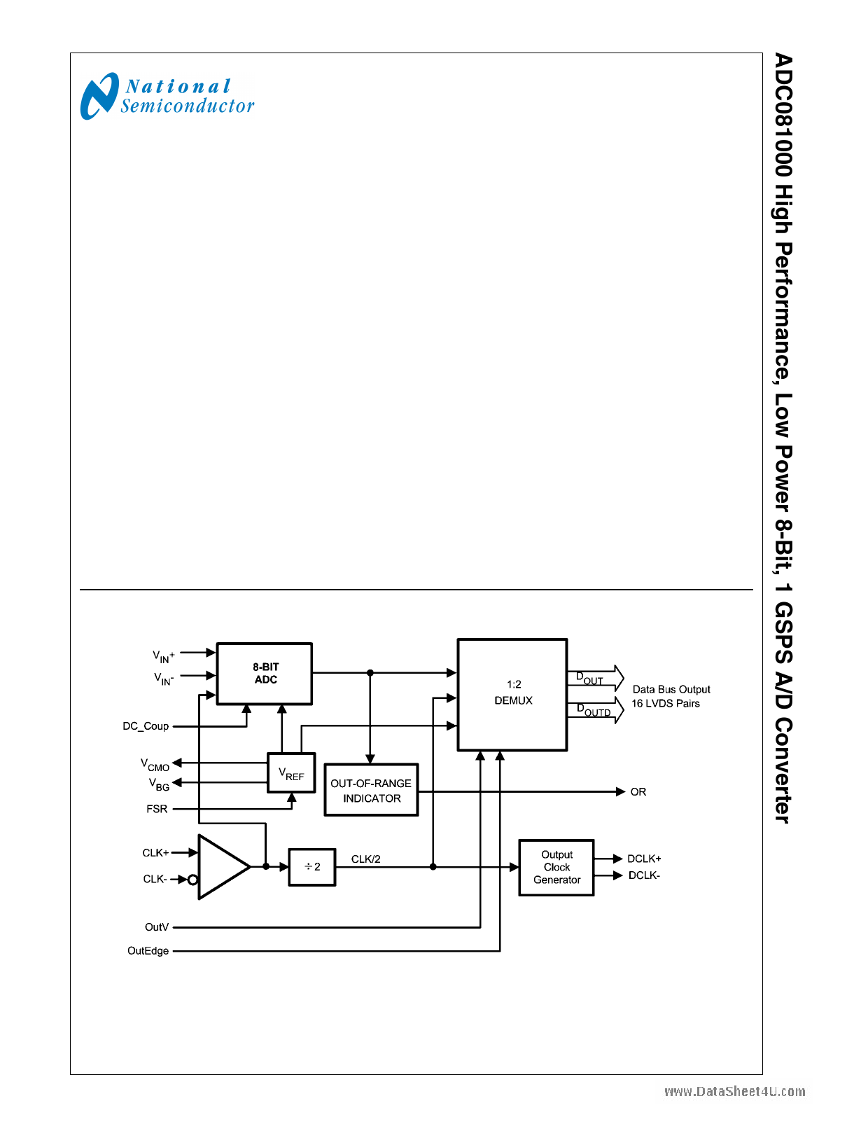
High Performance, Low Power 8-Bit, 1 GSPS A/D Converter
General Description
The ADC081000 is a low power, high performance CMOS
analog-to-digital converter that digitizes signals to 8 bits res-
olution at sampling rates up to 1.6 GSPS. Consuming a typical
1.4 Watts at 1 GSPS from a single 1.9 Volt supply, this device
is guaranteed to have no missing codes over the full operating
temperature range. The unique folding and interpolating ar-
chitecture, the fully differential comparator design, the inno-
vative design of the internal sample-and-hold amplifier and
the self-calibration scheme enable a very flat response of all
dynamic parameters beyond Nyquist, producing a high 7.5
ENOB with a 500 MHz input signal and a 1 GHz sample rate
while providing a 10-18 B.E.R. Output formatting is offset bi-
nary and the LVDS digital outputs are compliant with IEEE
1596.3-1996, with the exception of a reduced common mode
voltage of 0.8V.
The converter has a 1:2 demultiplexer that feeds two LVDS
buses, reducing the output data rate on each bus to half the
sampling rate. The data on these buses are interleaved in
time to provide a 500 MHz output rate per bus and a combined
output rate of 1 GSPS.
The converter typically consumes less than 10 mW in the
Power Down Mode and is available in a 128-lead, thermally
enhanced exposed pad LQFP and operates over the indus-
trial (-40°C ≤ TA ≤ +85°C) temperature range.
Features
■ Internal Sample-and-Hold
■ Single +1.9V ±0.1V Operation
■ Adjustable Output Levels
■ Guaranteed No Missing Codes
■ Low Power Standby Mode
Key Specifications
■ Resolution
■ Max Conversion Rate
■ ENOB @ 500 MHz Input
■ DNL
■ Conversion Latency
■ Power Consumption
■ — Operating
— Power Down Mode
Applications
■ Direct RF Down Conversion
■ Digital Oscilloscopes
■ Satellite Set-top boxes
■ Communications Systems
■ Test Instrumentation
8 Bits
1 GSPS (min)
7.5 Bits (typ)
±0.25 LSB (typ)
7 and 8 Clock Cycles
1.45 W (typ)
9 mW (typ)
Block Diagram
© 2009 National Semiconductor Corporation 200681
20068153
www.national.com
1 page 
Pin Functions
Pin No.
83
84
85
86
89
90
91
92
93
94
95
96
100
101
102
103
104
105
106
107
111
112
113
114
115
116
117
118
122
123
124
125
79
80
Symbol
D7-
D7+
D6-
D6+
D5-
D5+
D4-
D4+
D3-
D3+
D2-
D2+
D1-
D1+
D0-
D0+
Dd7-
Dd7+
Dd6-
Dd6+
Dd5-
Dd5+
Dd4-
Dd4+
Dd3-
Dd3+
Dd2-
Dd2+
Dd1-
Dd1+
Dd0-
Dd0+
OR+
OR-
82
81
2, 5, 8, 13, 16,
17, 20, 25, 28,
33, 128
40, 51, 62, 73,
88, 99, 110, 121
1, 6, 9, 12, 15,
21, 24, 27
42, 53, 64, 74,
87, 97, 108, 119
22, 23, 29, 34,
36 - 39,
41, 43 - 50, 52,
54 - 61, 63,
65 - 72,
75 - 78, 98, 109,
120
DCLK+
DCLK-
VA
VDR
GND
DR GND
NC
Equivalent Circuit
Description
www.DataSheet4U.com
LVDS data output bits sampled second in time sequence.
These outputs should always be terminated with a differential
100Ω resistance.
LVDS data output bits sampled first in time sequence. These
outputs should always be terminated with a differential
100Ω resistance.
Out of Range output. A differential high at these pins
indicates that the differential input is out of range (outside the
range of ±300 mV or ±400 mV as defined by the FSR pin).
See Section 1.6.
Differential Clock Outputs used to latch the output data.
Delayed and non-delayed data outputs are supplied
synchronous to this signal.
Analog power supply pins. Bypass these pins to GND.
Output Driver power supply pins. Bypass these pins to DR
GND.
Ground return for VA
Ground return for VDR
No Connection. Make no connection to these pins.
5 www.national.com
5 Page 
SIGNAL TO NOISE RATIO (SNR) is the ratio, expressed in
dB, of the rms value of the input signal at the output to the rms
value of the sum of all other spectral components below one-
half the sampling frequency, not including harmonics or d.c.
SIGNAL TO NOISE PLUS DISTORTION (S/(N+D) or
SINAD) is the ratio, expressed in dB, of the rms value of the
input signal at the output to the rms value of all of the other
spectral components below half the clock frequency, includ-
ing harmonics but excluding d.c.
SPURIOUS FREE DYNAMIC RANGE (SFDR) is the differ-
ence, expressed in dB, between the rms values of the input
signal at the output and the peak spurious signal, where a
spurious signal is any signal present in the output spectrum
that is not present at the input, excluding d.c.
TOTAL HARMONIC DISTORTION (THD) is the ratio ex-
pressed in dB, of the rms total of the first nine harmonic levels
at the output to the level of the fundamental at the output. THD
is calculated as
www.DataSheet4U.com
where Af1 is the RMS power of the fundamental (output) fre-
quency and Af2 through Af10 are the RMS power of the first 9
harmonic frequencies in the output spectrum.
– Second Harmonic Distortion (2nd Harm) is the differ-
ence, expressed in dB, between the RMS power in the input
frequency seen at the output and the power in its 2nd har-
monic level at the output.
– Third Harmonic Distortion (3rd Harm) is the difference
expressed in dB between the RMS power in the input fre-
quency seen at the output and the power in its 3rd harmonic
level at the output.
11 www.national.com
11 Page | ||
| Páginas | Total 30 Páginas | |
| PDF Descargar | [ Datasheet ADC081000.PDF ] | |
Hoja de datos destacado
| Número de pieza | Descripción | Fabricantes |
| ADC08100 | 8-Bit/ 20 MSPS to 100 MSPS/ 1.3 mW/MSPS A/D Converter | National Semiconductor |
| ADC08100 | ADC08100 8-Bit 20 Msps to 100 Msps 1.3 mW/Msps A/D Converter (Rev. I) | Texas Instruments |
| ADC081000 | 1 GSPS A/D Converter | National Semiconductor |
| ADC081000 | ADC081000 High Performance Low Power 8-Bit 1 GSPS A/D Converter (Rev. G) | Texas Instruments |
| Número de pieza | Descripción | Fabricantes |
| SLA6805M | High Voltage 3 phase Motor Driver IC. |
Sanken |
| SDC1742 | 12- and 14-Bit Hybrid Synchro / Resolver-to-Digital Converters. |
Analog Devices |
|
DataSheet.es es una pagina web que funciona como un repositorio de manuales o hoja de datos de muchos de los productos más populares, |
| DataSheet.es | 2020 | Privacy Policy | Contacto | Buscar |