|
|
|
PDF SC2446A Data sheet ( Hoja de datos )
| Número de pieza | SC2446A | |
| Descripción | Dual-Phase Single or Two Output Synchronous Step-Down Controller | |
| Fabricantes | Semtech Corporation | |
| Logotipo | ||
Hay una vista previa y un enlace de descarga de SC2446A (archivo pdf) en la parte inferior de esta página. Total 27 Páginas | ||
|
No Preview Available !
SC2446A
Dual-Phase, Single or Dual Output
Synchronous Step-Dwowww.DnataCShoeent4tUr.coomller
POWER MANAGEMENT
Description
The SC2446A is a high-frequency dual synchronous step-
down switching power supply controller. It provides out-
of-phase output gate signals. The SC2446A operates in
synchronous continuous-conduction mode. Both phases
are capable of maintaining regulation with sourcing or
sinking load currents, making the SC2446A suitable for
generating both VDDQ and the tracking VTT for DDR appli-
cations.
The SC2446A employs fixed frequency peak current-
mode control for the ease of frequency compensation
and fast transient response.
The dual-phase step-down controllers of the SC2446A
can be configured to provide two individually controlled
and regulated outputs or a single output with shared
current in each phase. The Step-down controllers oper-
ate from an input of at least 4.7V and are capable of
regulating outputs as low as 0.5V
The step-down controllers in the SC2446A have the pro-
vision to sense inductor RDC voltage drop for current-mode
control. This sensing scheme eliminates the need of the
current-sense resistor and is more noise-immune than
direct sensing of the high-side or the low-side MOSFET
voltage. Precise current-sensing with sense resistor is
optional.
Individual soft-start and overload shutdown timer is in-
cluded in each step-down controller. The SC2446A imple-
ments hiccup overload protection. In two-phase single-
output configuration, the master timer controls the soft-
start and overload shutdown functions of both control-
lers.
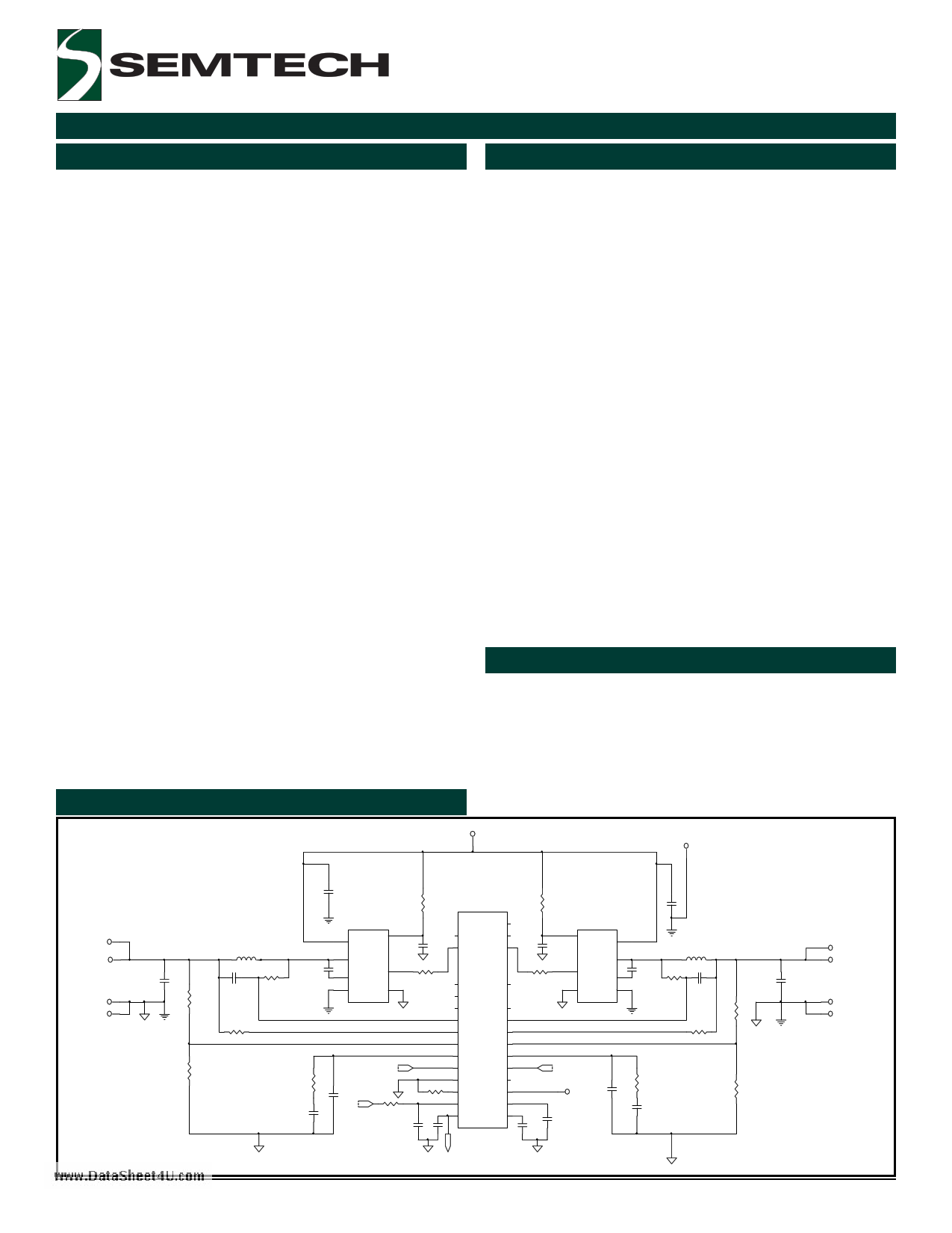
Typical Application Circuit
Features
2-Phase synchronous continuous conduction mode
for high efficiency step-down converters
Out of phase operation for low input current ripples
Output source and sink currents
Fixed frequency peak current-mode control
50mV/-75mV maximum current sense voltage
Inductive current-sensing for low-cost applications
Optional resistor current-sensing for precise cur-
rent-limit
Dual outputs or 2-phase single output operation
Excellent current sharing between individual phases
Wide input voltage range: 4.7V to 16V
Individual soft-start, overload shutdown and enable
Duty cycle up to 88%
0.5V feedback voltage for low-voltage outputs
External reference input for DDR applications
Programmable frequency up to 1MHz per phase
External synchronization
Industrial temperature range
28-lead TSSOP lead free package. This product is
fully WEEE and RoHS compliant
Applications
Telecommunication power supplies
DDR memory power supplies
Graphic power supplies
Servers and base stations
V IN (1 2 V )
V IN G N D
VO1
C 74
VO1GND
L6
C 62
R 13
R CS-6
R 46
R 28
Figure 1
Revision: November 9, 2005
C6
R 55
R49 C7
1 VDDO
U 10
VDDC 13
C 45 10 VO
11 CB
28 VSSO
VI 16
VSSC 9
In te gra te d M O S F E T /D rive r
C 68
R 53
0
REF OUT (0. 5V)
R 29
C 29
C 40
VIN
R 47
R 45
C72 C73
26 BST1
25 GDH 1
PVCC
B ST2
GDH 2
23
19
20
24 GD L1
GD L2 21
22 PGND
27 VPN 1
VPN 2 18
1 CS1+
CS2+ 14
2 CS1-
CS2- 13
4 IN1-
IN2- 12
5 COMP1
COMP2 11
8 REF
REFIN 10
7 AGND
VIN 2 17
3 Rosc
SYNC 6
16 AVCC
SS1/EN 1 28
9 R EFOU T SS2/EN 2 15
C 67
R 52
0
U9
13 VDDC
VDDO 1
16 VI
9 VSSC
VO 10
CB 11
VSSO 28
C 65
In te gra te d M O S F E T /D rive r
REF OUT (0. 5V)
TP11
C 70
C 71
R 48
C 63
C 64
U3
SC2446A
REF OUT (0. 5V)
L5
R14 C23
R CS-5
1
VO2
C 75
R 50
VO2GND
R 51
www.semtech.com
1 page 
POWER MANAGEMENT
Pin Configurations
TOP VIEW
CS1+
CS1-
ROSC
IN1-
COMP1
SYNC
AGND
REF
REFOUT
REFIN
COMP2
IN2-
CS2-
CS2+
1
2
3
4
5
6
7
8
9
10
11
12
13
14
28
27
26
25
24
23
22
21
20
19
18
17
16
15
SS1/EN1
VPN1
BST1
GDH1
GDL1
PVCC
PGND
GDL2
GDH2
BST2
VPN2
VIN2
AVCC
SS2/EN2
(28 Pin TSSOP)
Figure 2
SC2446A
www.DataSheet4U.com
Ordering Information
Device
SC2446AITSTRT(1)(2)
Package
TSSOP-28
Temp. Range( TA)
-40 to 125°C
SC2446AEVB
Evaluation Board
Notes:
(1) Only available in tape and reel packaging. A reel
contains 2500 devices for TSSOP package.
(2) Lead free product. This product is fully WEEE and
RoHS compliant.
2005 Semtech Corp.
5
www.semtech.com
5 Page 
SC2446A
POWER MANAGEMENT
Application Information (Cont.)
Setting the Switching Frequency
www.DataSheet4U.com
The switching frequency is set with an external resistor
connected from Pin 3 to the ground. The set frequency
is inversely proportional to the resistor value (Figure 5).
800
700
600
500
400
300
200
100
0
0
50 100 150 200 250
Rosc (k Ohm)
The followings are to be considered when choosing
inductors.
a) Inductor core material: For high efficiency applications
above 350KHz, ferrite, Kool-Mu and polypermalloy
materials should be used. Low-cost powdered iron cores
can be used for cost sensitive-applications below 350KHz
but with attendant higher core losses.
b) Select inductance value: Sometimes the calculated
inductance value is not available off-the-shelf. The
designer can choose the adjacent (larger) standard
inductance value. The inductance varies with
temperature and DC current. It is a good engineering
practice to re-evaluate the resultant current ripple at
the rated DC output current.
c) Current rating: The saturation current of the inductor
should be at least 1.5 times of the peak inductor current
under all conditions.
Figure 5. Free running frequency vs. ROSC.
Inductor (L) and Ripple Current
Both step-down controllers in the SC2446A operate in
synchronous continuous-conduction mode (CCM)
regardless of the output load. The output inductor
selection/design is based on the output DC and transient
requirements. Both output current and voltage ripples
are reduced with larger inductors but it takes longer to
change the inductor current during load transients.
Conversely smaller inductors results in lower DC copper
losses but the AC core losses (flux swing) and the winding
AC resistance losses are higher. A compromise is to
choose the inductance such that peak-to-peak inductor
ripple-current is 20% to 30% of the rated output load
current.
Assuming that the inductor current ripple (peak-to-peak)
value is δ*Io, the inductance value will then be
L
=
Vo (1− D) .
δIo fs
The peak current in the inductor becomes (1+δ/2)*Io
and the RMS current is
IL,rms = Io
1
+
δ2
12
.
Output Capacitor (Co) and Vout Ripple
The output capacitor provides output current filtering in
steady state and serves as a reservoir during load
transient. The output capacitor can be modeled as an
ideal capacitor in series with its parasitic ESR (Resr) and
ESL (Lesl) (Figure 6).
Co
Lesl
Resr
Figure 6. An equivalent circuit of Co.
If the current through the branch is ib(t), the voltage
across the terminals will then be
∫vo (t) =
Vo
+
1
Co
t
ib (t)dt + Lesl
0
dib (t)
dt
+
R esr ib
(t).
This basic equation illustrates the effect of ESR, ESL
and Co on the output voltage.
The first term is the DC voltage across Co at time t=0.
The second term is the voltage variation caused by the
2005 Semtech Corp.
11
www.semtech.com
11 Page | ||
| Páginas | Total 27 Páginas | |
| PDF Descargar | [ Datasheet SC2446A.PDF ] | |
Hoja de datos destacado
| Número de pieza | Descripción | Fabricantes |
| SC2446 | Dual-Phase Single or Two Output Synchronous Step-Down Controller | Semtech Corporation |
| SC2446A | Dual-Phase Single or Two Output Synchronous Step-Down Controller | Semtech Corporation |
| Número de pieza | Descripción | Fabricantes |
| SLA6805M | High Voltage 3 phase Motor Driver IC. |
Sanken |
| SDC1742 | 12- and 14-Bit Hybrid Synchro / Resolver-to-Digital Converters. |
Analog Devices |
|
DataSheet.es es una pagina web que funciona como un repositorio de manuales o hoja de datos de muchos de los productos más populares, |
| DataSheet.es | 2020 | Privacy Policy | Contacto | Buscar |