|
|
|
PDF ICS873033 Data sheet ( Hoja de datos )
| Número de pieza | ICS873033 | |
| Descripción | 3.3V 5V LVPECL/ECL CLOCK GENERATOR | |
| Fabricantes | Integrated Circuit Systems | |
| Logotipo | ||
Hay una vista previa y un enlace de descarga de ICS873033 (archivo pdf) en la parte inferior de esta página. Total 16 Páginas | ||
|
No Preview Available !
Integrated
Circuit
Systems, Inc.
ICS873033www.DataSheet4U.com
HIGH SPEED, ÷4 DIFFERENTIAL-TO-
3.3V, 5V LVPECL/ECL CLOCK GENERATOR
GENERAL DESCRIPTION
The ICS873033 is a high speed, high perfor-
ICS mance Differential-to-3.3V, 5V LVPECL/ECL
HiPerClockS™ Clock Generator a n d a m e m b e r o f t h e
HiPerClockS ™ family of High Performance
Clock Solutions from ICS. The ICS873033
is characterized to operate from either a 3.3V or a 5V
power supply.
FEATURES
• One differential 3.3V, 5V LVPECL / ECL output
• One differential PCLK, nPCLK input pair
• PCLK, nPCLK pair can accept the following
differential input levels: LVPECL, LVDS, CML, SSTL
• Input frequency: 3.2GHz (maximum)
• Translates any single ended input signal to 3.3V
LVPECL levels with resistor bias on nPCLK input
• Additive phase jitter, RMS: 0.20ps (typical)
• LVPECL mode operating voltage supply range:
VCC = 3.0V to 5.5V, VEE = 0V
• ECL mode operating voltage supply range:
VCC = 0V, VEE = -5.5V to -3.0V
• -40°C to 85°C ambient operating temperature
• Available in both standard and lead-free RoHS-compliant
packages
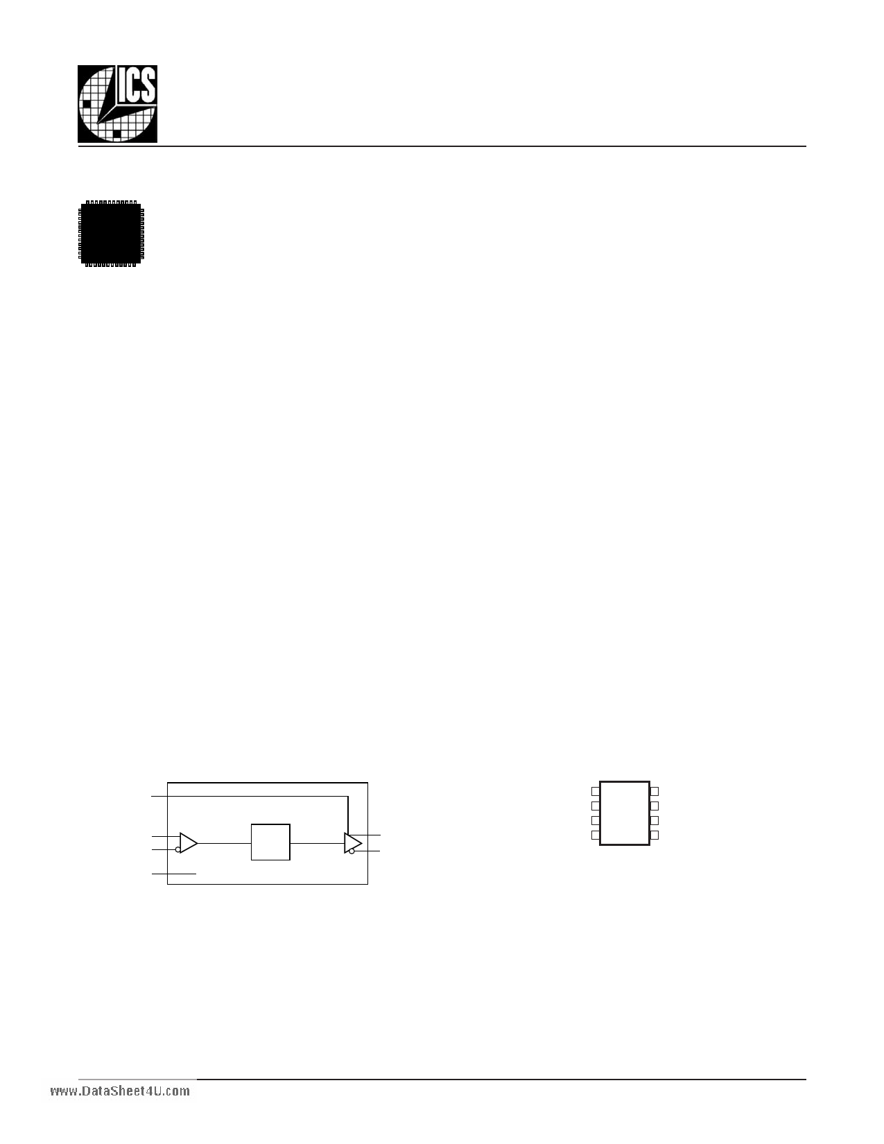
BLOCK DIAGRAM
PIN ASSIGNMENT
RESET
PCLK
nPCLK
VBB
RESET 1
8 Vcc
PCLK 2
7Q
Q
÷4 nQ
nPCLK 3
VBB 4
6 nQ
5 VEE
ICS873033
8-Lead SOIC
3.90mm x 4.90mm x 1.37mm package body
M Package
Top View
ICS873033
8-Lead TSSOP, 118 mil
3mm x 3mm x 0.95mm package body
G Package
Top View
The Preliminary Information presented herein represents a product in prototyping or pre-production. The noted characteristics are based on initial
product characterization. Integrated Circuit Systems, Incorporated (ICS) reserves the right to change any circuitry or specifications without notice.
873033AM
www.icst.com/products/hiperclocks.html
REV. A OCTOBER 19, 2005
1
1 page 
Integrated
Circuit
Systems, Inc.
ICS873033www.DataSheet4U.com
HIGH SPEED, ÷4 DIFFERENTIAL-TO-
3.3V, 5V LVPECL/ECL CLOCK GENERATOR
TABLE 5. AC CHARACTERISTICS, VCC = 0V; VEE = -5.5V TO -3.0V OR VCC = 3.0V TO 5.5V; VEE = 0V
Symbol Parameter
-40°C
25°C
Min Typ Max Min Typ Max Min
f
MAX
tPD
tjit(Ø)
Input Frequency
Propagation Delay; NOTE 1
Buffer Additive Phase Jitter, RMS;
155.52MHz, Integration Range
12kHz - 20MHz; Refer to Additive
Phase Jitter Section
3.2 3.2
300 475 300 430 530 350
0.20 0.20
tRR Set/Reset Recovery; NOTE 2
150 100
200 100
200
tR/tF Output Rise/Fall Time 20% to 80% 100
250 100
250 100
tPW Pulse Width; NOTE 3 RESET 550 480
All parameters are measured at f ≤ 1.7GHz, unless otherwise noted.
550 480
550
NOTE 1: Measured from the differential input crossing point to the differential output crossing point.
NOTE 2: See Figure 1, Timing Diagram.
85°C
Typ
450
Max
3.2
550
0.20
100
250
480
Units
GHz
ps
ps
ps
ps
ps
873033AM
www.icst.com/products/hiperclocks.html
5
REV. A OCTOBER 19, 2005
5 Page 
Integrated
Circuit
Systems, Inc.
ICS873033www.DataSheet4U.com
HIGH SPEED, ÷4 DIFFERENTIAL-TO-
3.3V, 5V LVPECL/ECL CLOCK GENERATOR
POWER CONSIDERATIONS
This section provides information on power dissipation and junction temperature for the ICS873033.
Equations and example calculations are also provided.
1. Power Dissipation.
The total power dissipation for the ICS873033 is the sum of the core power plus the power dissipated in the load(s).
The following is the power dissipation for V = 5.5V, which gives worst case results.
CC
NOTE: Please refer to Section 3 for details on calculating power dissipated in the load.
• Power (core) = V * I = 5.5V * 30mA = 165mW
MAX
CC_MAX EE_MAX
• Power (outputs)MAX = 30.94mW/Loaded Output pair
Total Power (5.5V, with all outputs switching) = 165mW + 30.94mW = 195.94mW
_MAX
2. Junction Temperature.
Junction temperature, Tj, is the temperature at the junction of the bond wire and bond pad and directly affects the reliability of the
device.The maximum recommended junction temperature for HiPerClockSTM devices is 125°C.
The equation for Tj is as follows: Tj = θJA * Pd_total + TA
Tj = Junction Temperature
θJA = Junction-to-Ambient Thermal Resistance
Pd_total = Total Device Power Dissipation (example calculation is in section 1 above)
TA = Ambient Temperature
In order to calculate junction temperature, the appropriate junction-to-ambient thermal resistance θJA must be used. Assuming a
moderate air flow of 200 linear feet per minute and a multi-layer board, the appropriate value is 103.3°C/W per Table 6A below.
Therefore, Tj for an ambient temperature of 85°C with all outputs switching is:
85°C + 0.196W * 103.3°C/W = 105.2°C. This is well below the limit of 125°C.
This calculation is only an example.Tj will obviously vary depending on the number of loaded outputs, supply voltage, air flow,
and the type of board (single layer or multi-layer).
TABLE 6A. THERMAL RESISTANCE θJA FOR 8-PIN SOIC, FORCED CONVECTION
θJA by Velocity (Linear Feet per Minute)
Single-Layer PCB, JEDEC Standard Test Boards
Multi-Layer PCB, JEDEC Standard Test Boards
0
153.3°C/W
112.7°C/W
200
128.5°C/W
103.3°C/W
500
115.5°C/W
97.1°C/W
NOTE: Most modern PCB designs use multi-layered boards.The data in the second row pertains to most designs.
TABLE 6B. THERMAL RESISTANCE θJA FOR 8-PIN TSSOP, FORCED CONVECTION
θJA by Velocity (Meters per Second)
01
Multi-Layer PCB, JEDEC Standard Test Boards
101.7°C/W
90.5°C/W
873033AM
www.icst.com/products/hiperclocks.html
11
2
89.8°C/W
REV. A OCTOBER 19, 2005
11 Page | ||
| Páginas | Total 16 Páginas | |
| PDF Descargar | [ Datasheet ICS873033.PDF ] | |
Hoja de datos destacado
| Número de pieza | Descripción | Fabricantes |
| ICS873032 | 5V LVPECL/ECL CLOCK GENERATOR | Integrated Circuit System |
| ICS873033 | 3.3V 5V LVPECL/ECL CLOCK GENERATOR | Integrated Circuit Systems |
| ICS873033 | HIGH SPEED 4 DIFFERENTIAL-TO- 3.3V 5V LVPECL/ECL CLOCK GENERATOR | Integrated Circuit Systems |
| ICS873034 | 3.3V LVPECL/ECL CLOCK GENERATOR | Integrated Circuit System |
| Número de pieza | Descripción | Fabricantes |
| SLA6805M | High Voltage 3 phase Motor Driver IC. |
Sanken |
| SDC1742 | 12- and 14-Bit Hybrid Synchro / Resolver-to-Digital Converters. |
Analog Devices |
|
DataSheet.es es una pagina web que funciona como un repositorio de manuales o hoja de datos de muchos de los productos más populares, |
| DataSheet.es | 2020 | Privacy Policy | Contacto | Buscar |