|
|
|
PDF LX2205 Data sheet ( Hoja de datos )
| Número de pieza | LX2205 | |
| Descripción | 1A Li-Ion Battery Charger | |
| Fabricantes | Microsemi Corporation | |
| Logotipo | ||
Hay una vista previa y un enlace de descarga de LX2205 (archivo pdf) en la parte inferior de esta página. Total 14 Páginas | ||
|
No Preview Available !
LX2205
TM ® 1A Li-Ion Battery Charger with Power wSwowu.rDcaetaMShaeneat4gUe.cmoment
PRODUCTION DATA SHEET
DESCRIPTION
The LX2205 is a complete single two logically selectable levels (100mA
cell Lithium Ion or Lithium Polymer and 500mA). When powered by a USB
battery charger and power source input, the battery is charged with the
manager. In addition to battery excess USB current that is not
charging, power flow control is consumed by the system load. If the
provided from up to three sources: a load exceeds the USB current limit, the
wall adapter, a standard USB power battery will discharge to assist the USB
plug or the battery.
power source to power the load. The
The battery charge current and controller can logically suspend the
termination current are independently USB power to allow the system to
adjustable. The controller also operate from the battery without
includes status indicators which show loading the USB.
when the controller is powered by an When a wall adapter is applied, it
external adapter in addition to charge takes precedent over the USB power
in progress, and charge completed. input and disables the USB input to
The USB input is current limited at prevent current flow from the adapter to
the USB port.
IMPORTANT: For the most current data, consult MICROSEMI’s website: http://www.microsemi.com
Patents Pending.
KEY FEATURES
Single Cell Li-Ion Battery Charger
Power Source Management
Up to 1A Charging Current
Integrated Power MOSFET
USB Current Compliance
25µA Quiescent Current in
Discharge Mode
Taper Current Termination
Protection features:
o USB Reverse Current Blocking
o Unsafe Battery Temp Lockout
o Internal IC Temperature Limiter
o USB Current Limiter
APPLICATIONS
Navigation Devices
Portable USB Devices
Multi-Media Player
PDA Phones
Digital Cameras
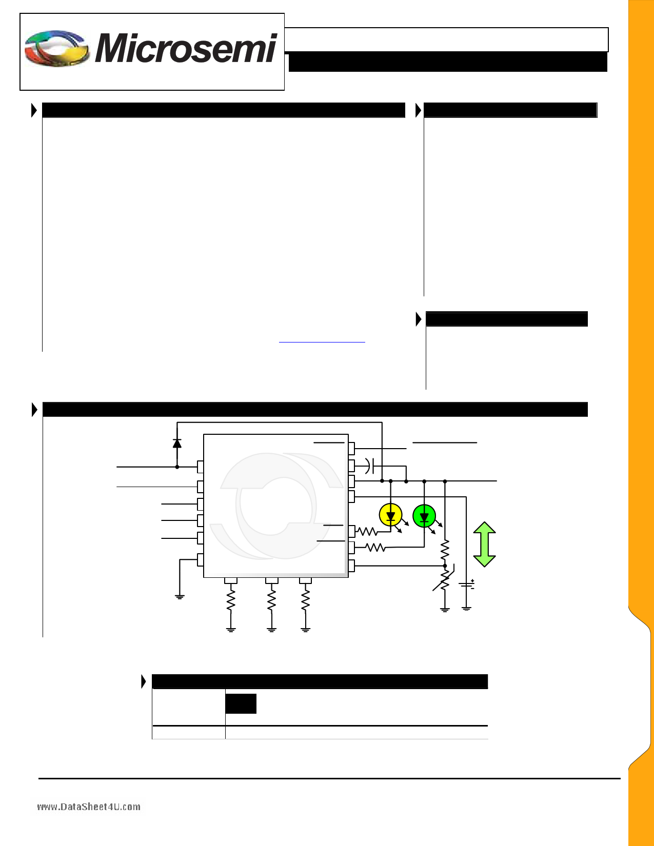
PRODUCT HIGHLIGHT
Wall Adapter
USB Power
Suspend
High/Low
Shutdown
DC OK
MDC
USB LX2205
SUSP
CMP
SYS
BAT
UCL
SHDN
GND
CCP
CTP
CHG
DONE
CUS TFB
Adapter Present
System Load
Thermistor
Charge/
Discharge
Li-Ion
Copyright © 2007
Rev. 1.0a, 2007-03-02
PACKAGE ORDER INFO
TA (°C)
-40 to 85
LQ
Plastic MLP 4 x 4mm 16 pin
RoHS Compliant / Pb-free
LX2205ILQ
Note: Available in Tape & Reel. Append the letters “TR” to the part number. (i.e. LX2205ILQ-TR)
Microsemi
Analog Mixed Signal Group
11861 Western Avenue, Garden Grove, CA. 92841, 714-898-8121, Fax: 714-893-2570
Page 1
1 page 
LX2205
TM ® 1A Li-Ion Battery Charger with Power wSwowu.rDcaetaMShaeneat4gUe.cmoment
PRODUCTION DATA SHEET
ELECTRICAL CHARACTERISTICS (CONTINUED)
Unless otherwise specified, the following specifications apply over the operating temperature -40ºC ≤ TA ≤ 85 ºC and the following test
conditions: VMDC = VUSB = 5V, VSYS =Open, VSUSP = VSHDN = Low, VUCL = High, VBAT = 3.9V, RCCP = 49.9k, RCUS = 2.26k, RCTP = 20k
Parameter
` USB CURRENT LIMIT
Symbol
Test Conditions
LX2205
Units
Min Typ Max
USB Low Current Limit
USB High Current Limit
Reverse Leakage Current
IUSB
IUSB
ILEAK
VMDC = 0V, UCL = Low
VMDC = 0V
VUSB = 0V
85 93 100
425 463 500
2 10
mA
mA
µA
CUS Bias Voltage
` LOGIC
CHG , DONE Logic High Output
CHG , DONE Logic Low Output
Input Logic : UCL, SUSP, SHDN
VCUS
VOH
VOL
VLOG(IN)
VSYS = 5.0V, IOH = -25uA
VSYS = 5.0V, IOL = 5mA
Logic Hi,
Logic Lo
2.5
4.0 4.5
0.4
1.2
0.4
V
V
V
V
Input Logic Current : UCL, SUSP,
SHDN
ILOG(IN)
Logic Hi, VLOG = 2V
Logic Lo, VLOG = 0V
024
-2 0 2
µA
Output Logic : DC OK
` THERMAL DIE PROTECTION
VLOG(OUT)
Logic Hi, 10K to 3.3V
Logic Lo, ILOG = 100µA
3.2
V
0.4
Battery Charger Thermal Limiter
TCTL
` BI-DIRECTIONAL PASS ELEMENT CONTROL
140 °C
Discharge Switch On Resistance
RDS(ON)
IBAT = -1A
275 mΩ
Charging Threshold
Discharging Threshold
Pass Element Switch Mode Delay
Charging headroom
Discharging headroom
` MDC INPUT
VCHG
VDCH
tsw
VSYS – VBAT
VBAT – VSYS
Charge–To–Discharge or Discharge–To–Charge
VSYS – VBAT, IBAT = 5mA
VBAT – VSYS, IBAT = -20mA
40
40
2.5
80
80
mV
mV
µs
mV
mV
DC OK Voltage Threshold
VMDC
Rising
Hysteresis
VMDC(HYS)
MDC Input current
IMDC
` BATTERY TEMPERATURE MONITOR
4.0 4.15 4.3
35
15 35
V
mV
µA
Cold Temp Fault Threshold
VTFB(COLD)
Rising Threshold ; as % of VSYS
Falling Threshold; as % of VSYS
73 75 77
71 73 75
%
%
Hot Temp Fault Threshold
TFB Disable Voltage Threshold
VTFB(HOT)
VTFB(DIS)
Falling Threshold; as % of VSYS
Rising Threshold; as % of VSYS
27 28.5 30
28 29.5 31
70 100 150
%
%
mV
Copyright © 2007
Rev. 1.0a, 2007-03-02
Microsemi
Analog Mixed Signal Group
11861 Western Avenue, Garden Grove, CA. 92841, 714-898-8121, Fax: 714-893-2570
Page 5
5 Page 
LX2205
TM ® 1A Li-Ion Battery Charger with Power wSwowu.rDcaetaMShaeneat4gUe.cmoment
PRODUCTION DATA SHEET
THEORY OF OPERATION / APPLICATION NOTE
MDC, USB OR-ING, UVLO AND DC OK
The power path from the USB input to the SYS pin
consists of a current limiter and a bidirectional switch
(capable of blocking current in either direction). The USB
input is switched off when at least one of the following
conditions exists:
1. VUSB < VUSBUVLO
2. USB Suspend pin is asserted.
3. VMDC > VUSB
4. VMDC > VDC OK _THRESHOLD
The MDC input is a monitoring input only, it is not a
high current input. When the voltage at SYS exceeds the
UVLO level, (typically 3.7V), the charger portion of the
circuit is activated. The DC OK output is pulled low when
both of the following conditions are true:
1. VMDC > VDC OK _THRESHOLD
2. VSYS > VBAT
Therefore when using a current limited wall adapter it is
possible to charge the battery and not assert the DC OK
output.
PROTECTION FEATURES
Conditioning Current Mode – If the battery terminal
voltage is less than 2.7V, the battery charger will reduce the
charge current to 5% of full scale. This also protects the
appliance from overheating by trying to drive the full
charging current into a short circuited battery.
Under Voltage Lockout – The charger remains inactive
until the under voltage lockout threshold is exceeded at the
SYS pin.
Thermal Control Loop – The power dissipation of the
charger is limited by reducing the charge current with a
control loop to prevent the die temperature from exceeded
approximately 140°C.
Reverse Current Blocking – Current will not flow out of
the USB pin.
Shutdown Mode – If the SHDN pin is logic high, the
charger enters a shutdown mode to prevent draining the
battery.
Battery Temperature Lockout – If an unsafe temperature is
sensed by the TFB input window comparator, battery
charging is suspended.
LAYOUT GUIDELINES
It is important when laying out the LX2205 to place
10µF ceramic capacitors as close to the SYS, USB and
VBAT IC terminals as possible to filter switching
transients.
It is important to provide a low thermal impedance path
from the thermal pad on the bottom of the LX2205
package to the ground plane of the circuit board to
maximize heat dissipation. Generally this is
accomplished by the use of multiple thermal vias.
The compensation capacitor should be placed close to
the CMP pin and connected with a short trace.
CHARGE CURRENT PROGRAMMING
The CCP, CTP, and CUS programming pins are used to
program the constant charge current, termination current,
and USB current, respectively. These pins utilize regulated
output voltages that produce a program current across an
external resistor to GND.
The following tables are guidelines for selecting the proper
resistor values:
Constant Charge Current (in mA)
50
RCCP
1270k
100 604k
200 294k
300 187k
400 137k
500 107k
600 88.7k
700 75.0k
800 63.4k
900 56.2k
1000
49.9k*
* RCCP minimum value
Termination Current (in mA)
5
RCTP
237k
10 105k
20 51.1k
40 24.9k
60 15.8k
80 11.8k
100 9.09k
120 7.50k
140 6.34k
160 5.49k
180 4.75k
200 4.22k
Copyright © 2007
Rev. 1.0a, 2007-03-02
Microsemi
Analog Mixed Signal Group
11861 Western Avenue, Garden Grove, CA. 92841, 714-898-8121, Fax: 714-893-2570
Page 11
11 Page | ||
| Páginas | Total 14 Páginas | |
| PDF Descargar | [ Datasheet LX2205.PDF ] | |
Hoja de datos destacado
| Número de pieza | Descripción | Fabricantes |
| LX2201 | USB Li-Ion Battery Charger | Microsemi Corporation |
| LX2202 | 2A Li-Ion Linear Charger and Power Control | Microsemi Corporation |
| LX2203 | Li-Ion Battery Charger | Microsemi Corporation |
| LX2203A | Li-Ion Battery Charger | Microsemi Corporation |
| Número de pieza | Descripción | Fabricantes |
| SLA6805M | High Voltage 3 phase Motor Driver IC. |
Sanken |
| SDC1742 | 12- and 14-Bit Hybrid Synchro / Resolver-to-Digital Converters. |
Analog Devices |
|
DataSheet.es es una pagina web que funciona como un repositorio de manuales o hoja de datos de muchos de los productos más populares, |
| DataSheet.es | 2020 | Privacy Policy | Contacto | Buscar |