|
|
|
PDF LTM4614 Data sheet ( Hoja de datos )
| Número de pieza | LTM4614 | |
| Descripción | Dual 4A per Channel Low VIN DC/DC uModule Regulator | |
| Fabricantes | Linear Technology | |
| Logotipo | ||
Hay una vista previa y un enlace de descarga de LTM4614 (archivo pdf) en la parte inferior de esta página. Total 20 Páginas | ||
|
No Preview Available !
FEATURES
n Dual 4A Output Power Supply
n Input Voltage Range: 2.375V to 5.5V
n 4A DC Typical, 5A Peak Output Current Each
n 0.8V Up to 5V Output Each, Parallelable
n ±2% Total DC Output Error (0°C ≤ TJ ≤ 125°C)
n Output Voltage Tracking
n Up to 95% Efficiency
n Programmable Soft-Start
n Short-Circuit and Overtemperature Protection
n Power Good Indicators
n Small and Very Low Profile Package:
15mm × 15mm × 2.82mm
APPLICATIONS
n Telecom and Networking Equipment
n FPGA Power
n SERDES and Other Low Noise Applications
L, LT, LTC, LTM, μModule, Linear Technology and the Linear logo are registered trademarks
of Linear Technology Corporation. All other trademarks are the property of their respective
owners. Protected by U.S. Patents including 5481178, 6580258, 6304066, 6127815, 6498466,
6611131, 6724174.
LTM4614www.DataSheet4U.com
Dual 4A per Channel
Low VIN DC/DC
µModule Regulator
DESCRIPTION
The LTM®4614 is a complete 4A dual output switching
mode DC/DC power supply. Included in the package are
the switching controllers, power FETs, inductors and all
support components. The dual 4A DC/DC converters
operate over an input voltage range of 2.375V to 5.5V.
The LTM4614 supports output voltages ranging from 0.8V
to 5V. The regulator output voltages are set by a single
resistor for each output. Only bulk input and output ca-
pacitors are needed to complete the design.
The low profile package (2.82mm) enables utilization of
unused space on the bottom of PC boards for high density
point of load regulation.
Additional features include overvoltage protection, foldback
overcurrent protection, thermal shutdown and programmable
soft-start. The power module is offered in a space saving
and thermally enhanced 15mm × 15mm × 2.82mm LGA
package. The LTM4614 is Pb-free and RoHS compliant.
Different Combinations of Input and Output Voltages
NUMBER OF INPUTS NUMBER OF OUTPUTS
22
IOUT(MAX)
4A, 4A
2 (Current Share,
Ex. 3.3V and 5V)
1
8A
1 2 4A, 4A
1 1 8A, see LTM4608A
TYPICAL APPLICATION
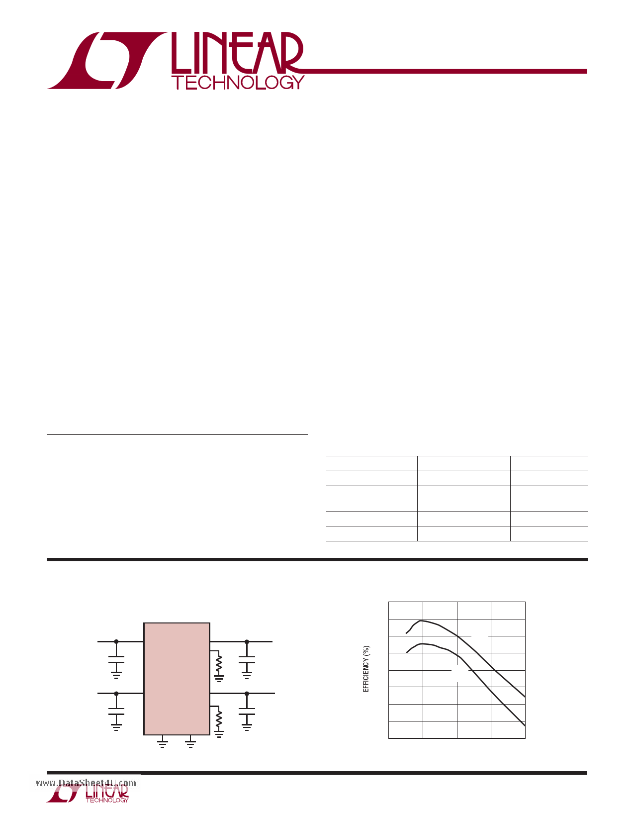
Dual Output 4A DC/DC μModule® Regulator
VIN1
3.3V TO 5V
VIN2
3.3V TO 5V
VIN1
VOUT1
FB1
10μF
LTM4614
VIN2
10μF
VOUT2
FB2
GND1 GND2
10k
5.76k
VOUT1
1.2V/4A
100μF
VOUT2
1.5V/4A
100μF
4614 F01a
Efficiency vs Output Current
91
VIN = 3.3V
89
87 VOUT
1.5V
85
83 VOUT
1.2V
81
79
77
75
0
12 3
LOAD CURRENT (A)
4
4614 TA01b
4614fa
1
1 page 
TYPICAL PERFORMANCE CHARACTERISTICS
LTM4614www.DataSheet4U.com
Start-Up
Start-Up
VOUT
1V/DIV
IIN
1A/DIV
VOUT
1V/DIV
IIN
1A/DIV
VIN = 5V
VOUT = 2.5V
COUT = 100μF
NO LOAD
200μs/DIV
(0.01μF SOFT-START CAPACITOR)
4614 G10
VIN = 5V
VOUT = 2.5V
COUT = 100μF
4A LOAD
200μs/DIV
(0.01μF SOFT-START CAPACITOR)
Current Limit Foldback
1.6
1.4
1.2
1.0
0.8
0.6
0.4 VOUT = 1.5V
VIN = 5V
0.2 VIN = 3.3V
VIN = 2.5V
0
345
6
OUTPUT CURRENT (A)
7
8
4614 G13
Short-Circuit Protection
1.5V Short, No Load
VOUT
0.5V/DIV
IIN
4A/DIV
20μs/DIV
VFB vs Temperature
806
804
802
800
4614 G11
798
796
794
–50 –25
0 25 50 75
TEMPERATURE (°C)
100 125
4614 G12
Short-Circuit Protection
1.5V Short, 4A Load
VOUT
0.5V/DIV
IIN
1A/DIV
4614 G14
100μs/DIV
4614 G15
4614fa
5
5 Page 
LTM4614www.DataSheet4U.com
APPLICATIONS INFORMATION
TRACK1 is the track ramp applied to the slave’s track pin.
TRACK1 applies the track reference for the slave output up
to the point of the programmed value at which TRACK1
proceeds beyond the 0.8V reference value. The TRACK1
pin must go beyond the 0.8V to ensure the slave output
has reached its final value.
Ratiometric tracking can be achieved by a few simple
calculations and the slew rate value applied to the master’s
TRACK pin. As mentioned above, the TRACK pin has a
control range from 0V to 0.8V. The control ramp slew rate
applied to the master’s TRACK pin is directly equal to the
master’s output slew rate in Volts/Time.
The equation:
MR
SR
•
4.99k
=
RTB
where MR is the master’s output slew rate and SR is the
slave’s output slew rate in Volts/Time. When coincident
tracking is desired, then MR and SR are equal, thus RTB
is equal to 4.99k. RTA is derived from equation:
RTA =
VFB
0.8V
+ VFB – VTRACK
4.99k RFB RTB
where VFB is the feedback voltage reference of the regula-
tor, and VTRACK is 0.8V. Since RTB is equal to the 4.99k top
feedback resistor of the slave regulator in equal slew rate
or coincident tracking, then RTA is equal to RFB with VFB =
VTRACK. Therefore RTB = 4.99k and RTA = 10k in Figure 2.
Figure 3 shows the output voltage tracking waveform for
coincident tracking.
In ratiometric tracking, a different slew rate maybe desired
for the slave regulator. RTB can be solved for when SR is
slower than MR. Make sure that the slave supply slew rate
is chosen to be fast enough so that the slave output voltage
will reach it final value before the master output.
For example, MR = 2.5V/ms and SR = 1.8V/1ms. Then
RTB = 6.98k. Solve for RTA to equal to 3.24k. The master
output must be greater than the slave output for the
tracking to work. Output load current must be present
for tracking to operate properly during power down.
Power Good
PGOOD1 and PGOOD2 are open-drain pins that can be
used to monitor valid output voltage regulation. These pins
monitor a ±7.5% window around the regulation point.
COMP Pin
This pin is the external compensation pin. The module has
already been internally compensated for all output voltages.
Table 4 is provided for most application requirements.
The Linear Technology μModule Power Design Tool will
be provided for other control loop optimization.
MASTER OUTPUT
SLAVE OUTPUT
TIME
4614 F03
Figure 3. Output Voltage Coincident Tracking
4614fa
11
11 Page | ||
| Páginas | Total 20 Páginas | |
| PDF Descargar | [ Datasheet LTM4614.PDF ] | |
Hoja de datos destacado
| Número de pieza | Descripción | Fabricantes |
| LTM4611 | 15A DC/DC uModule Regulator | Linear Technology |
| LTM4611 | 15A DC/DC uModule Regulator | Linear Technology |
| LTM4612 | DC/DC uModule | Linear Technology |
| LTM4613 | DC/DC uModule Regulator | Linear Technology |
| Número de pieza | Descripción | Fabricantes |
| SLA6805M | High Voltage 3 phase Motor Driver IC. |
Sanken |
| SDC1742 | 12- and 14-Bit Hybrid Synchro / Resolver-to-Digital Converters. |
Analog Devices |
|
DataSheet.es es una pagina web que funciona como un repositorio de manuales o hoja de datos de muchos de los productos más populares, |
| DataSheet.es | 2020 | Privacy Policy | Contacto | Buscar |