|
|
|
PDF HV9918 Data sheet ( Hoja de datos )
| Número de pieza | HV9918 | |
| Descripción | High Brightness LED Driver | |
| Fabricantes | Supertex | |
| Logotipo | ||
Hay una vista previa y un enlace de descarga de HV9918 (archivo pdf) en la parte inferior de esta página. Total 7 Páginas | ||
|
No Preview Available !
HV9918
Hysteretic, Buck, High Brightness LED Driver
with High-Side Current Sensing
Features
► Hysteretic control with high-side current sensing
► Integrated 40V 1.0Ω MOSFET
► >90% Efficiency
► Wide input voltage range: 4.5 to 40V
► ±5% LED current accuracy
► Up to 2.0MHz switching frequency
► Adjustable constant LED current
► Analog or PWM control signal for PWM dimming
► Over-temperature protection
► -40ºC to +125ºC operating temperature range
Applications
► Low voltage industrial and architectural lighting
► General purpose constant current source
► Signage and decorative LED lighting
► Indicator and emergency lighting
www.DataSheet4U.com
General Description
The HV9918 is a PWM controller IC designed to drive high
brightness LEDs using a buck topology. It operates from an input
voltage of 4.5 to 40VDC and employs hysteretic control with a
high-side current sense resistor to set the constant output current
up to 700mA. The device is well suited for applications requiring
a wide input voltage range. The high-side current sensing and an
integrated current-setting circuitry minimize the number of external
components while delivering an accurate average output.
Dedicated pulse-width modulation (PWM) input enables pulsed
LED dimming over a wide range of brightness levels. A hysteretic
control method ensures excellent input supply rejection and fast
response during load transients and PWM dimming.
The HV9918 offers an analog-controlled PWM dimming feature
that reduces the output current by applying an external DC voltage
below the internal 2.0V threshold voltage from ADIM to GND. ADIM
can also accept input from a resistor divider including a negative
temperature coefficient (NTC) thermistor connected between
ADIM and GND, or a positive temperature coefficient (PTC)
thermistor connected between ADIM and VDD thus providing a
PWM thermal-foldback feature that reduces the LED current when
the temperature of the LED string exceeds a specified temperature
point. Additional features include thermal-shutdown protection.
The high switching frequency up to 2.0MHz permits the use of
small inductors and capacitors, minimizing space and cost in the
overall system.
The HV9918 comes in a small 8-Lead DFN package and is ideal
for industrial and general lighting applications.
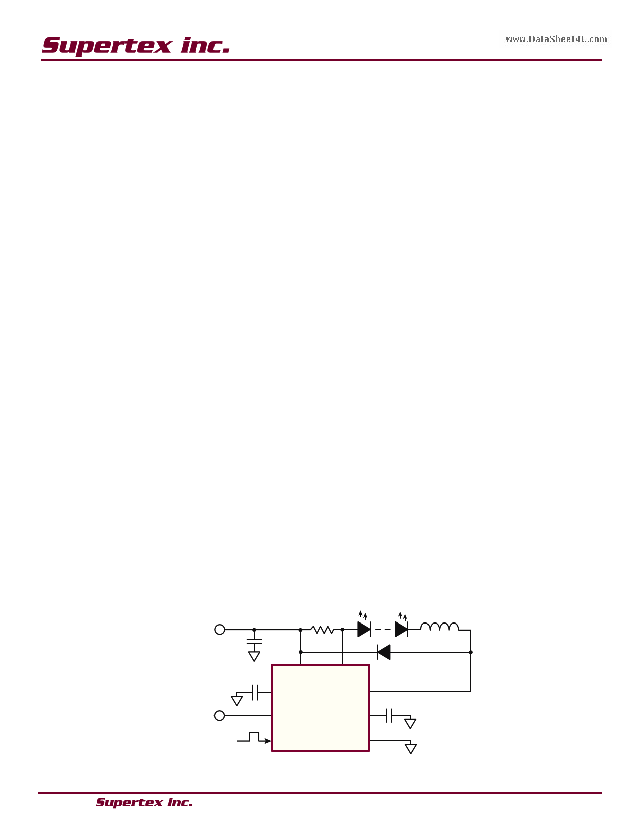
Typical Application Circuit
0 - 2.0V
RSENSE
CIN
VIN
RAMP
CS
SW
ADIM
VDD
DIM GND
HV9918
L
● 1235 Bordeaux Drive, Sunnyvale, CA 94089 ● Tel: 408-222-8888 ● www.supertex.com
1 page 
HV9918
One possible application of the ADIM feature of the HV9918
may include protection of the LED load from over-tempera-
ture by connecting an NTC thermistor at ADIM, as shown in
Figure 1.
VDD
HV9918
the inductor ramps up and the voltage across the sense re-
sistor reaches the upper threshold, the internal MOSFET at
SW turns off. The MOSFET turns on again when the inductor
current ramps down through the freewheeling diode until the
voltage across the sense resistor equals the lower threshold.
Use the following equation to determine the inductor value
for a desired value of operating frequency fS:
NTC
ADIM
L
=
(VIN - VOUT )VOUT
fSVIN ∆IO
-
(VIN
-
VOUT
∆IO
)tDPDL
-
VOUT tDPDH
∆IO
GND
Figure 1
Setting LED Current with External Resistor RSENSE
The output current in the LED is determined by the external
current sense resistor (RSENSE) connected between VIN and
CS. Disregarding the effect of the propagation delays, the
sense resistor can be calculated as:
RSENSE
≈
1
2
•
(VRS(HI) + VRS(LO)
ILED
)
=
200mV
ILED
Selecting Buck Inductor L
The HV9918 regulates the LED output current using an input
comparator with hysteresis (Figure 2). As the current through
where:
∆IO
=
V - VRS(HI)
RS(LO)
RSENSE
and tDPDL, tDPDH are the propagation delays. Note, that the cur-
rent ripple ∆I in the inductor L is greater than ∆IO. This ripple
can be calculated from the following equation:
∆I
=
∆IO
+
(VIN
-
VOUT)tDPDL
L
+
VOUT tDPDH
L
For the purpose of the proper inductor selection, note that
the maximum switching frequency occurs at the highest VIN
and VOUT = VIN/2.
www.DataSheet4U.com
VRS(HI)
RSENSE
ILED
VRS(LO)
RSENSE
tDPDL
tDPDH
TS
=
1
fS
ΔI ΔIO
VDIM
t
Figure 2
● 1235 Bordeaux Drive, Sunnyvale, CA 94089 ● Tel: 408-222-8888 ● www.supertex.com
5
t
5 Page | ||
| Páginas | Total 7 Páginas | |
| PDF Descargar | [ Datasheet HV9918.PDF ] | |
Hoja de datos destacado
| Número de pieza | Descripción | Fabricantes |
| HV9910 | Universal High Brightness LED Driver | Supertex |
| HV9910B | Universal High-Brightness LED Driver | Microchip |
| HV9910B | Universal High Brightness LED Driver | Supertex |
| HV9910C | Universal High-Brightness LED Driver | Microchip |
| Número de pieza | Descripción | Fabricantes |
| SLA6805M | High Voltage 3 phase Motor Driver IC. |
Sanken |
| SDC1742 | 12- and 14-Bit Hybrid Synchro / Resolver-to-Digital Converters. |
Analog Devices |
|
DataSheet.es es una pagina web que funciona como un repositorio de manuales o hoja de datos de muchos de los productos más populares, |
| DataSheet.es | 2020 | Privacy Policy | Contacto | Buscar |