|
|
|
PDF AD9122 Data sheet ( Hoja de datos )
| Número de pieza | AD9122 | |
| Descripción | Digital-to-Analog Converter | |
| Fabricantes | Analog Devices | |
| Logotipo | ||
Hay una vista previa y un enlace de descarga de AD9122 (archivo pdf) en la parte inferior de esta página. Total 30 Páginas | ||
|
No Preview Available !
Dual, 16-Bit, 1230 MSPS,
TxDAC+ Digital-to-Analog Converter
AD9122
FEATURES
Flexible LVDS interface allows word, byte, or nibble load
Single-carrier W-CDMA ACLR = 82 dBc at 122.88 MHz IF
Analog output: adjustable 8.7 mA to 31.7 mA,
RL = 25 Ω to 50 Ω
Integrated 2×/4×/8× interpolator/complex modulator allows
carrier placement anywhere in the DAC bandwidth
Gain, dc offset, and phase adjustment for sideband
suppression
Multiple chip synchronization interfaces
High performance, low noise PLL clock multiplier
Digital inverse sinc filter
Low power: 1.5 W at 1.2 GSPS, 800 mW at 500 MSPS,
full operating conditions
72-lead, exposed paddle LFCSP
APPLICATIONS
Wireless infrastructure
W-CDMA, CDMA2000, TD-SCDMA, WiMAX, GSM, LTE
Digital high or low IF synthesis
Transmit diversity
Wideband communications: LMDS/MMDS, point-to-point
GENERAL DESCRIPTION
The AD9122 is a dual, 16-bit, high dynamic range digital-to-
analog converter (DAC) that provides a sample rate of 1230 MSPS,
permitting multicarrier generation up to the Nyquist frequency.
The AD9122 TxDAC+® includes features optimized for direct
conversion transmit applications, including complex digital mod-
ulation, and gain and offset compensation. The DAC outputs
are optimized to interface seamlessly with analog quadrature
modulators, such as the ADL537x F-MOD series from Analog
Devices, Inc. A 4-wire serial port interface provides for program-
ming/readback of many internal parameters. Full-scale output
current can be programmed over a range of 8.7 mA to 31.7 mA.
The AD9122 comes in a 72-lead LFCSP.
PRODUCT HIGHLIGHTS
1. Ultralow noise and intermodulation distortion (IMD)
enable high quality synthesis of wideband signals from
baseband to high intermediate frequencies (IF).
2. Proprietary DAC output switching technique enhances
dynamic performance.
3. Current outputs are easily configured for various single-
ended or differential circuit topologies.
4. Flexible LVDS digital interface allows the standard 32-wire
bus to be reduced to one-half or one-quarter of the width.
COMPANION PRODUCTS
IQ Modulators: ADL5370, ADL537x family
IQ Modulators with PLL and VCO: ADRF6701, ADRF670x family
Clock Drivers: AD9516, AD951x family
Voltage Regulator Design Tool: ADIsimPower
Additional companion products on the AD9122 product page
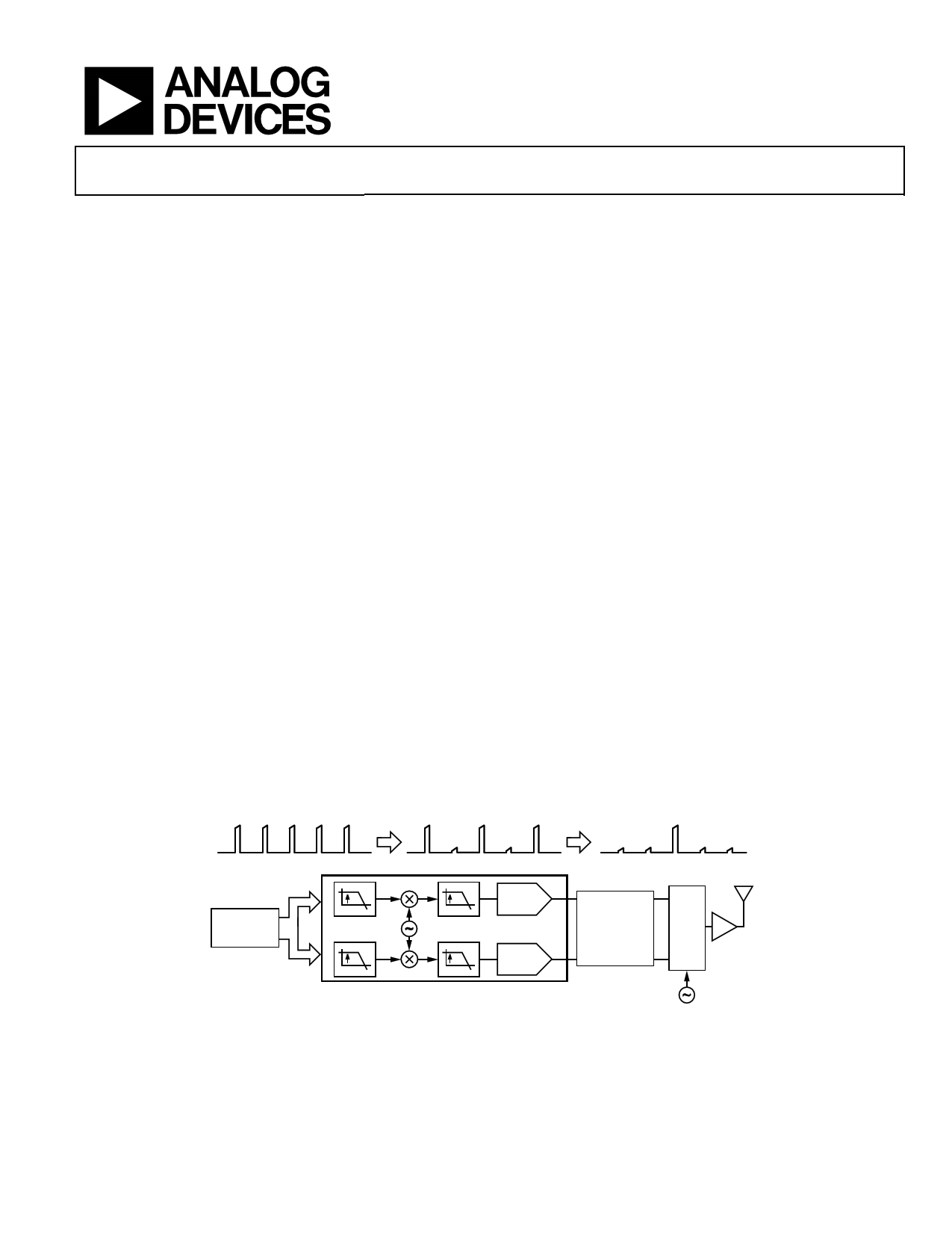
COMPLEX BASEBAND
TYPICAL SIGNAL CHAIN
COMPLEX IF
RF
DC fIF
DIGITAL
BASEBAND
PROCESSOR
2
SIN
COS
2
2/4 I DAC
2/4 Q DAC
NOTES
1. AQM = ANALOG QUADRATURE MODULATOR.
Figure 1.
LO – fIF
ANTIALIASING
FILTER
AQM PA
LO
Rev. B
Information furnished by Analog Devices is believed to be accurate and reliable. However, no
responsibility is assumed by Analog Devices for its use, nor for any infringements of patents or other
rights of third parties that may result from its use. Specifications subject to change without notice. No
license is granted by implication or otherwise under any patent or patent rights of Analog Devices.
Trademarksandregisteredtrademarksarethepropertyoftheirrespectiveowners.
One Technology Way, P.O. Box 9106, Norwood, MA 02062-9106, U.S.A.
Tel: 781.329.4700
www.analog.com
Fax: 781.461.3113 ©2009–2011 Analog Devices, Inc. All rights reserved.
1 page 
AD9122
SPECIFICATIONS
DC SPECIFICATIONS
TMIN to TMAX, AVDD33 = 3.3 V, DVDD18 = 1.8 V, CVDD18 = 1.8 V, IFS = 20 mA, maximum sample rate, unless otherwise noted.
Table 1.
Parameter
RESOLUTION
ACCURACY
Differential Nonlinearity (DNL)
Integral Nonlinearity (INL)
MAIN DAC OUTPUTS
Offset Error
Gain Error (with Internal Reference)
Full-Scale Output Current1
Output Compliance Range
Power Supply Rejection Ratio, AVDD33
Output Resistance
Gain DAC Monotonicity
Settling Time to Within ±0.5 LSB
MAIN DAC TEMPERATURE DRIFT
Offset
Gain
Reference Voltage
REFERENCE
Internal Reference Voltage
Output Resistance
ANALOG SUPPLY VOLTAGES
AVDD33
CVDD18
DIGITAL SUPPLY VOLTAGES
DVDD18
IOVDD
POWER CONSUMPTION
2× Mode, fDAC = 491.22 MSPS, IF = 10 MHz, PLL Off
2× Mode, fDAC = 491.22 MSPS, IF = 10 MHz, PLL On
8× Mode, fDAC = 800 MSPS, IF = 10 MHz, PLL Off
AVDD33
CVDD18
DVDD18
Power-Down Mode (Register 0x01 = 0xF0)
POWER-UP TIME
OPERATING RANGE
Min
−0.001
−3.6
8.66
−1.0
−0.3
3.13
1.71
1.71
1.71
−40
Typ
16
±2.1
±3.7
0
±2
19.6
10
Guaranteed
20
0.04
100
30
1.2
5
3.3
1.8
1.8
1.8/3.3
834
913
1135
55
85
444
6.5
260
+25
Max
+0.001
+3.6
31.66
+1.0
+0.3
3.47
1.89
1.89
3.47
1241
57
90
495
18.8
+85
Unit
Bits
LSB
LSB
% FSR
% FSR
mA
V
% FSR/V
MΩ
ns
ppm/°C
ppm/°C
ppm/°C
V
kΩ
V
V
V
V
mW
mW
mW
mA
mA
mA
mW
ms
°C
1 Based on a 10 kΩ external resistor between FSADJ and AVSS.
Rev. B | Page 5 of 60
5 Page 
TYPICAL PERFORMANCE CHARACTERISTICS
0 fDATA = 250MSPS, SECOND HARMONIC
–10 fDATA = 250MSPS, THIRD HARMONIC
fDATA = 400MSPS, SECOND HARMONIC
–20 fDATA = 400MSPS, THIRD HARMONIC
–30
–40
–50
–60
–70
–80
–90
–100
0
50 100 150 200 250 300 350 400 450
fOUT (MHz)
Figure 4. Harmonics vs. fOUT over fDATA, 2× Interpolation,
Digital Scale = 0 dBFS, IFS = 20 mA
0 fDATA = 100MSPS, SECOND HARMONIC
–10 fDATA = 100MSPS, THIRD HARMONIC
fDATA = 200MSPS, SECOND HARMONIC
–20 fDATA = 200MSPS, THIRD HARMONIC
–30
–40
–50
–60
–70
–80
–90
–100
0
50 100 150 200 250 300 350 400 450
fOUT (MHz)
Figure 5. Harmonics vs. fOUT over fDATA, 4× Interpolation,
Digital Scale = 0 dBFS, IFS = 20 mA
0
fDATA = 100MSPS, SECOND HARMONIC
–10 fDATA = 100MSPS, THIRD HARMONIC
fDATA = 150MSPS, SECOND HARMONIC
–20 fDATA = 150MSPS, THIRD HARMONIC
–30
–40
–50
–60
–70
–80
–90
–100
0
100 200 300 400 500 600 700
fOUT (MHz)
Figure 6. Harmonics vs. fOUT over fDATA, 8× Interpolation,
Digital Scale = 0 dBFS, IFS = 20 mA
AD9122
0
0dBFS
–10 –6dBFS
–12dBFS
–20 –18dBFS
–30
–40
–50
–60
–70
–80
–90
–100
0
50 100 150 200 250 300 350 400 450
fOUT (MHz)
Figure 7. Second Harmonic vs. fOUT over Digital Scale, 2× Interpolation,
fDATA = 400 MSPS, IFS = 20 mA
0
0dBFS
–10 –6dBFS
–12dBFS
–20 –18dBFS
–30
–40
–50
–60
–70
–80
–90
–100
0
50 100 150 200 250 300 350 400 450
fOUT (MHz)
Figure 8. Third Harmonic vs. fOUT over Digital Scale, 2× Interpolation,
fDATA = 400 MSPS, IFS = 20 mA
0
IFS = 10mA, SECOND HARMONIC
–10 IFS = 20mA, SECOND HARMONIC
IFS = 30mA, SECOND HARMONIC
–20 IFS = 10mA, THIRD HARMONIC
–30
IFS = 20mA, THIRD HARMONIC
IFS = 30mA, THIRD HARMONIC
–40
–50
–60
–70
–80
–90
–100
0
50 100 150 200 250 300 350 400 450
fOUT (MHz)
Figure 9. Harmonics vs. fOUT over IFS, 2× Interpolation,
fDATA = 400 MSPS, Digital Scale = 0 dBFS
Rev. B | Page 11 of 60
11 Page | ||
| Páginas | Total 30 Páginas | |
| PDF Descargar | [ Datasheet AD9122.PDF ] | |
Hoja de datos destacado
| Número de pieza | Descripción | Fabricantes |
| AD9121 | TxDAC+ Digital-to-Analog Converter | Analog Devices |
| AD9122 | Digital-to-Analog Converter | Analog Devices |
| AD9125 | TxDAC+ Digital-to-Analog Converter | Analog Devices |
| AD9129 | (AD9119 / AD9129) RF Digital-to-Analog Converter | Analog Devices |
| Número de pieza | Descripción | Fabricantes |
| SLA6805M | High Voltage 3 phase Motor Driver IC. |
Sanken |
| SDC1742 | 12- and 14-Bit Hybrid Synchro / Resolver-to-Digital Converters. |
Analog Devices |
|
DataSheet.es es una pagina web que funciona como un repositorio de manuales o hoja de datos de muchos de los productos más populares, |
| DataSheet.es | 2020 | Privacy Policy | Contacto | Buscar |