|
|
|
PDF NCP1631 Data sheet ( Hoja de datos )
| Número de pieza | NCP1631 | |
| Descripción | 2-Phase Power Factor Controller | |
| Fabricantes | ON Semiconductor | |
| Logotipo | ||
Hay una vista previa y un enlace de descarga de NCP1631 (archivo pdf) en la parte inferior de esta página. Total 24 Páginas | ||
|
No Preview Available !
NCP1631
Interleaved, 2-Phase Power
Factor Controller
The NCP1631 integrates a dual MOSFET driver for interleaved
PFC applications. Interleaving consists of paralleling two small
stages in lieu of a bigger one, more difficult to design. This approach
has several merits like the ease of implementation, the use of smaller
components or a better distribution of the heating.
Also, Interleaving extends the power range of Critical Conduction
Mode that is an efficient and cost−effective technique (no need for
low trr diodes). In addition, the NCP1631 drivers are 180° phase shift
for a significantly reduced current ripple.
Housed in a SOIC16 package, the circuit incorporates all the
features necessary for building robust and compact interleaved PFC
stages, with a minimum of external components.
General Features
• Near−Unity Power Factor
• Substantial 180° Phase Shift in All Conditions Including Transient
Phases
• Frequency Clamped Critical Conduction Mode (FCCrM) i.e.,
Fixed Frequency, Discontinuous Conduction Mode Operation with
Critical Conduction Achievable in Most Stressful Conditions
• FCCrM Operation Optimizes the PFC Stage Efficiency Over the
Load Range
• Out−of−phase Control for Low EMI and a Reduced rms Current in
the Bulk Capacitor
• Frequency Fold−back at Low Power to Further Improve the Light
Load Efficiency
• Accurate Zero Current Detection by Auxiliary Winding for Valley
Turn On
• Fast Line / Load Transient Compensation
• High Drive Capability: −500 mA / +800 mA
• Signal to Indicate that the PFC is Ready for Operation (“pfcOK”
Pin)
• VCC Range: from 10 V to 20 V
www.onsemi.com
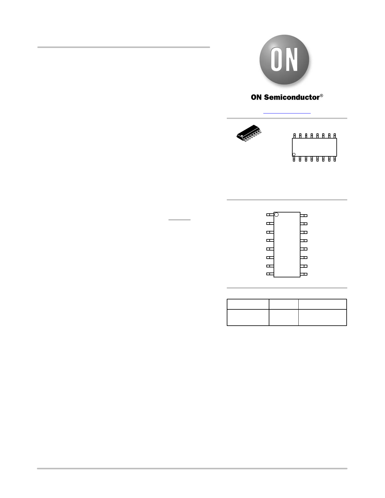
MARKING DIAGRAM
SOIC−16
D SUFFIX
CASE 751B
A
WL
Y
WW
G
NCP1631G
AWLYWW
= Assembly Location
= Wafer Lot
= Year
= Work Week
= Pb−Free Package
PIN ASSIGNMENT
ZCD2
FB
Rt
OSC
1
ZCD1
REF5V/pfcOK
DRV1
GND
Vcontrol
FFOLD
Vcc
DRV2
BO
OVP / UVP
(Top View)
Latch
CS
ORDERING INFORMATION
Device
Package
Shipping†
NCP1631DR2G SOIC−16 2500 / Tape & Reel
(Pb−Free)
†For information on tape and reel specifications,
including part orientation and tape sizes, please
refer to our Tape and Reel Packaging Specification
Brochure, BRD8011/D.
Safety Features
• Output Over and Under Voltage Protection
• Brown−Out Detection with a 50−ms Delay to Help
Meet Hold−up Time Specifications
• Soft−Start for Smooth Start−up Operation
• Programmable Adjustment of the Maximum Power
• Over Current Limitation
• Detection of Inrush Currents
Typical Applications
• Computer Power Supplies
• LCD / Plasma Flat Panels
• All Off Line Appliances Requiring Power Factor
Correction
*For additional information on our Pb−Free strategy and soldering details, please
download the ON Semiconductor Soldering and Mounting Techniques Reference
Manual, SOLDERRM/D.
© Semiconductor Components Industries, LLC, 2016
March, 2016 − Rev. 7
1
Publication Order Number:
NCP1631/D
1 page 
NCP1631
Table 2. TYPICAL ELECTRICAL CHARACTERISTICS TABLE (Conditions: VCC = 15 V, Vpin7 = 2 V, Vpin10 = 0 V; for typical
values TJ = 25°C, for min/max values TJ = −55°C to +125°C, unless otherwise specified) (Note 6)
Characteristics
Test Conditions
Symbol
Min Typ Max Unit
RAMP CONTROL (valid for the two phases)
Pin 3 voltage
Maximum Vton Voltage
Pin 3 Current Capability
Pin 3 sourced current below which the
controller is OFF
VBO = Vpin7 = 1.1 V, Ipin3 = 50 mA
VBO = Vpin7 = 1.1 V, Ipin3 = 200 mA
VBO = Vpin7 = 2.2 V, Ipin3 = 50 mA
VBO = Vpin7 = 2.2 V, Ipin3 = 200 mA
Not tested
VRt1
VRt2
VRt3
VRt4
Vton(MAX)
IRt(MAX)
IRt(off)
1.071
1.071
2.169
2.169
1
1.096
1.096
2.196
2.196
5
−
7
1.121
1.121
2.223
2.223
−
V
V
mA
mA
Pin 3 Current Range
Not tested
ZERO VOLTAGE DETECTION CIRCUIT (valid for ZCD1 and ZCD2)
IRt(range)
20
1000 mA
ZCD Threshold Voltage
ZCD Hysteresis
Input Clamp Voltage
High State
Low State
Internal Input Capacitance (Note 5)
ZCD Watchdog Delay
BROWN−OUT DETECTION
VZCD increasing
VZCD falling
VZCD decreasing
Ipin1 = 5.0 mA
Ipin1 = −5.0 mA
VZCD(TH),H
VZCD(TH),L
VZCD(HYS)
VZCD(high)
VZCD(low)
CZCD
tZCD
0.40 0.50 0.60
0.20 0.25 0.30
0.25
9.0 11 13
−1.1 −0.65 −0.1
− 10 −
80 200 320
V
V
V
pF
ms
Brown−Out Comparator Threshold
Brown−Out Current Source
Brown−Out Blanking Time (Note 5)
Brown−Out Monitoring Window (Note 5)
Pin 7 clamped voltage if VBO < VBO(TH)
during tBO(BLANK)
Current Capability of the BO Clamp
Hysteresis VBO(TH) – VBO(clamp)
Current Capability of the BO pin Clamp
PNP Transistor
TJ = −40°C to 125°C
TJ = −55°C to +125°C (Note 6)
TJ = −40°C to 125°C
TJ = −55°C to +125°C
Ipin7 = −100 mA
Ipin7 = − 100 mA
VBO(TH)
IBO
tBO(BLANK)
tBO(window)
VBO(clamp)
IBO(clamp)
VBO(HYS)
IBO(PNP)
0.97 1.00 1.03
V
67
5.7 7
8 mA
8
38 50 62 ms
38 50 63.5
38 50 62 ms
− 965 − mV
100 −
10 35
100 −
− mA
60 mV
− mA
Pin BO voltage when clamped by the PNP
OVER AND UNDER VOLTAGE PROTECTIONS
Ipin7 = − 100 mA
VBO(PNP)
0.35 0.70 0.90
V
Over−Voltage Protection Threshold
Ratio (VOVP / VREF) (Note 5)
Ratio UVP Threshold over VREF
Pin 8 Bias Current
LATCH INPUT
Vpin8 = 2.5 V
Vpin8 = 0.3 V
VOVP
VOVP/VREF
VUVP/VREF
IOVP(bias)
2.425
99.2
8
−500
2.500
99.7
12
−
2.575
100.2
16
500
V
%
%
nA
Pin Latch Threshold for Shutdown
VLatch
2.375 2.500 2.625 V
Product parametric performance is indicated in the Electrical Characteristics for the listed test conditions, unless otherwise noted. Product
performance may not be indicated by the Electrical Characteristics if operated under different conditions.
4. DRV1 and DRV2 pulsating at half this frequency, that is, 65 kHz.
5. Not tested. Guaranteed by design and characterization.
6. For coldest temperature, QA sampling at −40°C in production and −55°C specification is Guaranteed by Characterization.
www.onsemi.com
5
5 Page 
NCP1631
Given the regulation low bandwidth of the PFC systems,
(VCONTROL) and then (VREGUL) are slow varying signals.
Hence, the line current absorbed by each phase is:
Iin(phase1) + Iin(phase2) + k Vin
ƪ ƫwhere: k + constant +
CtVREGUL
2 L It
(eq. 6)
Hence, the input current is then proportional to the input
voltage and the ac line current is properly shaped.
One can note that this analysis is also valid for CrM
operation that is just a particular case of this functioning
where (t3=0), which leads to (t1+t2=Tsw) and
(VTON=VREGUL). That is why the NCP1631 automatically
adapts to the conditions and jumps from DCM and CrM
(and vice versa) without power factor degradation and
without discontinuity in the power delivery.
The charging current It is internally processed to be
proportional to the square of the line magnitude. Its value
is however programmed by the pin 3 resistor to adjust the
available on−time as defined by the Ton1 to Ton4 parameters
of the data sheet.
From these data, we can deduce:
t1
+
Ton(ms)
+
50
n
Rt 2
Vpin7
2
(eq. 7)
From this equation, we can check that if Vpin7 (BO
voltage) is 1 V and Rt is 20 kW (Ipin3 = 50 mA) that the
on−time is 20 ms as given by parameter Ton1.
Since:
VREGUL(max) + 1.66 V
Ton
+
CtVREGUL
It
2 Ǹ2
Vpin7 +
Vin(rms)
p
k
BO
where kBO is the scale down factor of the BO sensing
network
ǒ ǓkBO
+
Rbo2
Rbo1 ) Rbo2
(see Brown−out section)
We can deduce the total input current value and the
average input power:
Iin(rms)
^
26.9
(Rt)2VREGUL
@ 1012 L kBO 2Vin,rms
(eq. 8)
Pin,avg
^
(Rt)2VREGUL
26.9 @ 1012 L kBO
2
(eq. 9)
Figure 6. PWM Circuit and Timing Diagram
timing capacitor
s aw −too th
PWM
comparator
+ to PWM latch
−
VREGUL
R1
OA1 Vton
+
−
C1
S3
SKIP
OV P
OF F
OC P
0. 5*
IN 1 (I se nse
− 210 m)
S1
−> V ton d u ring (t1+t2)
S2
−> 0 V d u ring t3 (d e a d −time)
−> V ton *(t1+t2)/T in average
VBOcomp
(from BO block)
DT
(high during dead−time)
pfcOK
In−rus h
The integrator OA1 amplifies the error between VREGUL and
IN1 so that in average, (VTON*(t1+t2)/Tsw) equates VREGUL.
Figure 7. VTON Processing Circuit
The “VTON processing circuit” is “informed” when there
is an OVP condition or a skip sequence, not to
over−dimension VTON in that conditions. Otherwise, an
OVP sequence or a skipped cycle would be viewed as a
“normal” dead−time phase by the circuit and VTON would
inappropriately increase to compensate it. (Refer to
Figure 7).
The output of the “VTON processing circuit” is also
grounded when the circuit is in OFF state to discharge the
capacitor C1 and initialize it for the next active phase.
Finally, the “VTON” is not allowed to be further increased
compared to VREGUL when the circuit has not completed
the start−up phase (pfcOK low) and if VBOcomp from the
brown−out block is high (refer to brown−out section for
more information).
www.onsemi.com
11
11 Page | ||
| Páginas | Total 24 Páginas | |
| PDF Descargar | [ Datasheet NCP1631.PDF ] | |
Hoja de datos destacado
| Número de pieza | Descripción | Fabricantes |
| NCP163 | Ultra-Low Noise and High PSRR LDO Regulator | ON Semiconductor |
| NCP1631 | 2-Phase Power Factor Controller | ON Semiconductor |
| Número de pieza | Descripción | Fabricantes |
| SLA6805M | High Voltage 3 phase Motor Driver IC. |
Sanken |
| SDC1742 | 12- and 14-Bit Hybrid Synchro / Resolver-to-Digital Converters. |
Analog Devices |
|
DataSheet.es es una pagina web que funciona como un repositorio de manuales o hoja de datos de muchos de los productos más populares, |
| DataSheet.es | 2020 | Privacy Policy | Contacto | Buscar |