|
|
|
PDF ADIS16220 Data sheet ( Hoja de datos )
| Número de pieza | ADIS16220 | |
| Descripción | Programmable Digital Vibration Sensor | |
| Fabricantes | Analog Devices | |
| Logotipo | ||
Hay una vista previa y un enlace de descarga de ADIS16220 (archivo pdf) en la parte inferior de esta página. Total 16 Páginas | ||
|
No Preview Available !
www.DataSheet4U.com
Preliminary Technical Data
Programmable
Digital Vibration Sensor
ADIS16220
FEATURES
Digital ±70 g accelerometer/vibration sensing
22 kHz sensor resonance
100.2 kSPS sample rate
SPI-compatible serial interface
Programmable data capture function:
3 channels, 1024 samples each
1 accelerometer/2 auxiliary ADCs (AIN1, AIN2)
Manual trigger for user initiation
Automatic trigger for periodic data capture
Conditional trigger for condition-driven capture
Digital temperature sensor output
Digitally controlled sample rate
Digitally controlled frequency response
2 auxiliary digital I/Os
Digitally activated self-test
Digitally activated low power mode
Serial number and device ID
Single-supply operation: 3.15 V to 3.6 V
Operating temperature range: −40°C to +125°C
9.2 mm × 9.2 mm 16-terminal LGA
APPLICATIONS
Vibration analysis
Shock detection and event capture
Condition monitoring
Machine health
Instrumentation, diagnostics
Safety, shut-off sensing
Security sensing, tamper detection
GENERAL DESCRIPTION
The ADIS16220 iSensor® is a digital vibration sensor that com-
bines industry-leading iMEMS® sensing technology with a signal
processor. It provides a buffer memory for high speed data capture,
along with a convenient serial interface for data collection and
configuration. The 22 kHz sensor resonance and 100.2 kSPS
sample rate provide adequate response for most machine-health
applications. The averaging/decimating filter provides
optimization for lower bandwidth applications.
An internal clock drives the data sampling system, which fills
the buffer memory for user access. The data capture function
has three different trigger modes. The automatic data collection
allows for periodic wake-up and capture, based on a programma-
ble duty cycle. The manual data capture mode allows the user to
initiate a data capture, providing power and read-rate optimiza-
tion. The event capture mode continuously updates the buffers
and monitors them for a preset trigger condition. This mode
captures pre-event data and post-event data and produces an
alarm indicator for driving an interrupt.
The serial peripheral interface (SPI) and data buffer structure
provide convenient access to wide-bandwidth sensor data. The
ADIS16220 also offers a digital temperature sensor, digital
power supply measurements, and peak output capture.
The ADIS16220 comes in a 9.2 mm × 9.2 mm × 3.9 mm LGA
package that meets the Pb-free solder reflow profile require-
ments per JEDEC J-STD-020 and has an extended operating
temperature range of −40°C to +125°C.
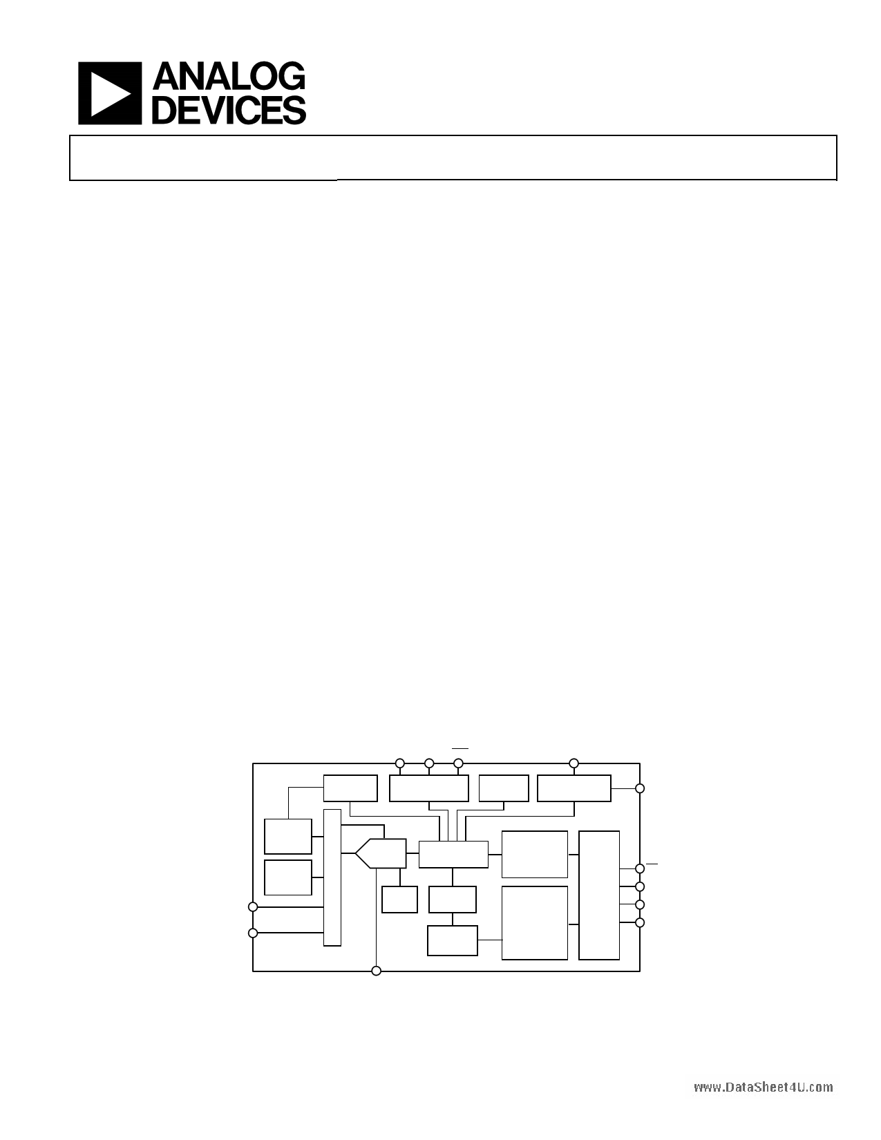
FUNCTION BLOCK DIAGRAM
DIO1 DIO2 RST
VDD
SELF-TEST
I/O
ALARMS
POWER
MANAGEMENT
GND
MEMS
SENSOR
AIN1
AIN2
TEMP
SENSOR
ADIS16220
CONTROLLER
CLOCK
FILTER
CAPTURE
BUFFER
USER
CONTROL
REGISTERS
OUTPUT
DATA
REGISTERS
SPI
PORT
VREF
Figure 1.
CS
SCLK
DIN
DOUT
Rev. PrD
Information furnished by Analog Devices is believed to be accurate and reliable. However, no
responsibility is assumed by Analog Devices for its use, nor for any infringements of patents or other
rights of third parties that may result from its use. Specifications subject to change without notice. No
license is granted by implication or otherwise under any patent or patent rights of Analog Devices.
Trademarksandregisteredtrademarksarethepropertyoftheirrespectiveowners.
One Technology Way, P.O. Box 9106, Norwood, MA 02062-9106, U.S.A.
Tel: 781.329.4700
www.analog.com
Fax: 781.461.3113
©2009 Analog Devices, Inc. All rights reserved.
1 page 
Preliminarywww.DataSheet4U.com Technical Data
TIMING SPECIFICATIONS
TA = 25°C, VDD = 3.3 V, unless otherwise noted.
Table 2.
Parameter
fSCLK
tSTALL
tCS
tDAV
tDSU
tDHD
tSCLKR, tSCLKF
tSR
tSF
tDF, tDR
tSFS
Description
SCLK frequency
Stall period between data, between 16th and 17th SCLK
Chip select to SCLK edge
DOUT valid after SCLK edge
DIN setup time before SCLK rising edge
DIN hold time after SCLK rising edge
SCLK rise/fall times
SCLK high pulse width
SCLK low pulse width
DOUT rise/fall times
CS high after SCLK edge
1 Guaranteed by design, not tested.
TIMING DIAGRAMS
ADIS16220
Min1
0.01
15.4
48.8
24.4
48.8
5
Typ Max
2.25
100
5 12.5
12.5
12.5
5 12.5
Unit
MHz
μs
ns
ns
ns
ns
ns
ns
ns
ns
ns
CS
SCLK
DOUT
DIN
tCS
1
MSB
W/R
tSR
tSF
23
4
56
tDAV
DB14
tDSU
DB13
DB12
tDHD
DB11
DB10
A6 A5 A4 A3 A2
Figure 2. SPI Timing and Sequence
15 16
tSFS
DB2
DB1 LSB
D2 D1 LSB
CS
SCLK
tSTALL
Figure 3. DIN Bit Sequence
Rev. PrD | Page 5 of 16
5 Page 
Preliminarywww.DataSheet4U.com Technical Data
ADIS16220
READING DATA FROM THE CAPTURE BUFFER
Initiate a manual capture command by setting GLOB_CMD[11]
= 1 (DIN = 0xBF08). Wait for DIO1 to go high and then low
before using the SPI port. When the capture is complete, the
first data samples load into the CAPT_BUFx registers and
0x0000 loads into the index pointer (CAPT_PNTR). The index
pointer determines which data samples load into the CAPT_BUFx
registers. For example, writing 0x0138 to the CAPT_PNTR
register (DIN = 0x9A38, DIN = 0x9B01) causes the 313th sample
in the buffer memory to load into the CAPT_BUFx registers.
CAPT_BUFA
ACCELERATION
CAPTURE
BUFFER
0
CAPT_PNTR
1023
Figure 14. Acceleration Capture Buffer Structure and Operation;
CAPT_BUF1 (AIN1) and CAPT_BUF2 (AIN2) Use Similar Structures
Table 9. CAPT_PNTR Bits Descriptions
Bit Description (Default = 0x0000)
[15:10]
Not used
[9:0] Data bits
The index pointer automatically increments with a CAPT_BUFA,
CAPT_BUF1, or CAPT_BUF2 read command. In the master
processor firmware, the loop may appear similar to the following:
Data(0) = spi_reg_read(0x14)
For n = 0 to 1023
Data(n) = spi_reg_read(0x14);
n = n + 1;
end
Output Data Format
The CAPT_BUFA and CAPT_PEAKA registers use a 14-bit, twos
complement format to accommodate acceleration in both direc-
tions (positive and negative). In addition to the acceleration data,
a capture event also produces analog input data (CAPT_BUF1,
CAPT_BUF2), power supply data (CAPT_SUPPLY), temperature
data (CAPT_TEMP), the peak acceleration level (CAPT_PEAKA)
and the peak analog input levels (CAPT_PEAK1, CAPT_PEAK2)
in the captured data.
Table 10. Capture Output Register Formats
Register
Bits Format
CAPT_SUPPLY 12 Binary, 0 V = 0 LSB
CAPT_TEMP 12 Binary, 25°C = 1278 LSB
CAPT_BUFA, 16
CAPT_PEAKA
Twos complement
CAPT_BUF1,
CAPT_BUF2,
CAPT_PEAK1,
CAPT_PEAK2
16
Twos complement
Scale
1.22 mV
−0.47°C
19.073 mg
350.18 μV
Table 11. Acceleration Data Format
Output (Binary)
Hex LSB
0000 1110 0101 0001 0x0E56 +3670
0000 0000 0000 0001 0x0001 +1
0000 0000 0000 0000 0x0000 0
1111 1111 1111 1111 0xFFFF −1
1111 0001 1010 1101 0xF1AA −3670
Acceleration
+70 g
+0.019073 g
0
−0.019073 g
−70 g
Table 12. Analog Input Data Format
Output (Binary)
Hex LSB
0000 1100 1100 1101 0x0CCD +3277
0000 0000 0000 0001 0x0001 +1
0000 0000 0000 0000 0x0000 0
1111 1111 1111 1111 0xFFFF −1
1111 0011 0011 0010 0xF332 -3277
Level (mV)
VDD/2 + 1000
VDD/2 + 0.305
VDD/2
VDD/2 − 0.305
VDD/2 − 1000
Power Supply Voltage (VS) Equation
VS = (CAPT_SUPPLY) × 0.001221 V/LSB = +3.3 V
where CAPT_SUPPLY = 2703 LSB.
Temperature Equation
Temperature = (1278 − CAPT_TEMP) × 0.47°C/LSB +
25°C = 0.1°C
where CAPT_TEMP = 1331.
CAPTURE MODE CONFIGURATION
The CAPT_CTRL register provides three different options for
triggering a data capture: manual, automatic, and event. It also
offers an option for placing the device in a low power, shutdown
mode in between capture events. This setting adds approximately
2.3 ms to the total capture time relationship:
TC
= 0.014
+
1
97,184
× 1024 × 2 AVG _ CNT (no flash)
TC
= 0.516
+
1
97,184
× 1024 × 2 AVG _ CNT (with
flash)
Table 13. CAPT_CTRL Bit Descriptions
Bit Description
(Default = 0x0020)
[15:7] Not used
[6] Automatically store capture buffers to flash upon alarm
trigger (1 = enabled)
[5:4] Pre-event capture length
00 = 64 samples
01 = 128 samples
10 = 256 samples
11 = 512 samples
[3:2] Capture mode
00 = manual: use GLOB_CMD[11] to start capture
01 = automatic: use CAPT_PRD[9:0] to set capture period
10 = event: continuously monitor data for the conditions
set in ALM_CTRL, ALM_MAGA, ALM_MAG1, and ALM_MAG2.
11 = not used
[1] Power-down between capture events
1 = enabled, which requires CS toggle to wake up
[0] Not used
Rev. PrD | Page 11 of 16
11 Page | ||
| Páginas | Total 16 Páginas | |
| PDF Descargar | [ Datasheet ADIS16220.PDF ] | |
Hoja de datos destacado
| Número de pieza | Descripción | Fabricantes |
| ADIS16220 | Programmable Digital Vibration Sensor | Analog Devices |
| ADIS16223 | Digital Tri-Axial Vibration Sensor | Analog Devices |
| ADIS16227 | Digital Tri-Axial Vibration Sensor | Analog Devices |
| ADIS16228 | Digital Tri-Axial Vibration Sensor | Analog Devices |
| Número de pieza | Descripción | Fabricantes |
| SLA6805M | High Voltage 3 phase Motor Driver IC. |
Sanken |
| SDC1742 | 12- and 14-Bit Hybrid Synchro / Resolver-to-Digital Converters. |
Analog Devices |
|
DataSheet.es es una pagina web que funciona como un repositorio de manuales o hoja de datos de muchos de los productos más populares, |
| DataSheet.es | 2020 | Privacy Policy | Contacto | Buscar |