|
|
|
PDF HMC665LP4E Data sheet ( Hoja de datos )
| Número de pieza | HMC665LP4E | |
| Descripción | GaAs MMIC MIXER w/ INTEGRATED IF & LO AMPLIFIER | |
| Fabricantes | Hittite Microwave Corporation | |
| Logotipo | ||
Hay una vista previa y un enlace de descarga de HMC665LP4E (archivo pdf) en la parte inferior de esta página. Total 10 Páginas | ||
|
No Preview Available !
v00.0508
10
Typical Applications
The HMC665LP4 / HMC665LP4E is ideal for:
• Cellular/3G & WiMAX/LTE/4G Infrastructure
• Base Stations & Repeaters
• Broadband & Fixed Wireless
• Access Points
• Test & Measurement Equipment
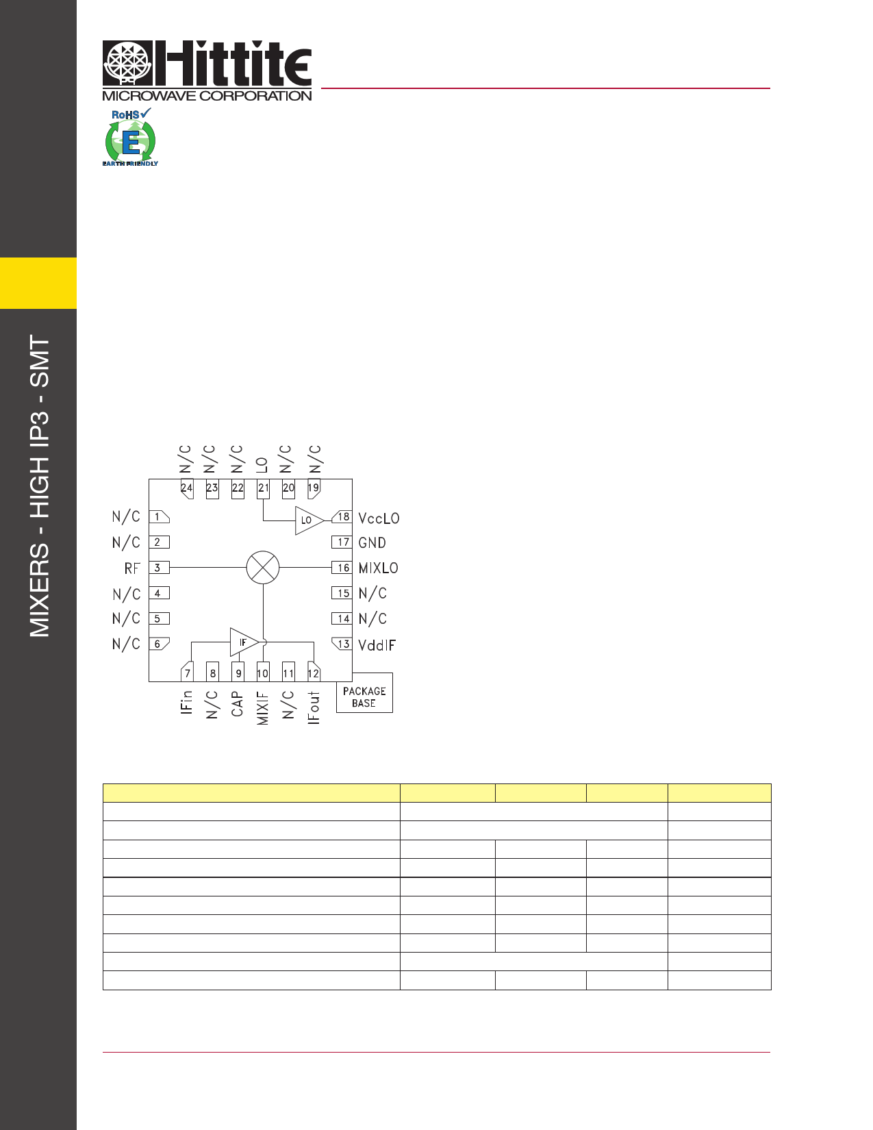
Functional Diagram
HMC665LP4 / 665LP4E
GaAs MMIC MIXER w/ INTEGRATED
IF & LO AMPLIFIER, 0.7 - 1.2 GHz
Features
High Input IP3: +23 dBm
Low Input LO Drive: -3 to +6 dBm
High LO to RF Isolation: 36 dB
High Conversion Gain: 10 dB
Ideal for Upconversion or Downconversion
24 Lead 4x4mm SMT Package: 16mm2
General Description
The HMC665LP4E is a highly integrated converter IC
that operates from 0.7 to 1.2 GHz for both up-conversion
and downconversion applications. The HMC665LP4E
incorporates a high dynamic range, passive double-
balanced mixer core with integrated LO and IF
amplifiers, making it ideal for compact transceiver
applications in GSM, WCDMA, TD-SCDMA, WiBro
and WiMAX. This versatile converter RFIC operates
with a low LO input power level of only -3 dBm,
provides up to 10 dB conversion gain, and exhibits
+23 dBm Input IP3 in downconversion mode. This RFIC
provides up to 11 dB conversion gain in upconverter
mode. Specific evaluation boards are available for
both upconverter and downconverter modes.
Electrical Specifications, TA = +25° C, LO = 0 dBm, VccLO= VddIF = +5V
Parameter
Min.
Typ. Max.
Units
Frequency Range, RF, LO
0.7 - 1.2
GHz
Frequency Range, IF
250 - 450
MHz
Conversion Gain
7 10
dB
Noise Figure (SSB)
10 dB
LO to RF Isolation
32 36
dB
LO to IF Isolation
1 dB
IP3 (Input)
23 dBm
1 dB Compression (Input)
10 dBm
LO Drive Input Level (Typical)
-3 to +6
dBm
Supply Current (IddIF + IccLO)
150 200
mA
*Unless otherwise noted, all measurements performed as a downconverter and configured as shown in the downconverter mode application
circuit, IF=250 MHz
10 - 1
For price, delivery and to place orders: Hittite Microwave Corporation, 20 Alpha Road, Chelmsford, MA 01824
Phone: 978-250-3343 Fax: 978-250-3373 Order On-line at www.hittite.com
Application Support: Phone: 978-250-3343 or [email protected]
1 page 
10
v00.0508
HMC665LP4 / 665LP4E
GaAs MMIC MIXER w/ INTEGRATED
IF & LO AMPLIFIER, 0.7 - 1.2 GHz
Typical Performance Cascade Analysis HMC665LP4E Downconverter Mode
(RF Input = 700 to 1200 MHz, IF Output = 250 to 450 MHz, LO = Low Side or High Side)
Component Level
Description
Gain
(dB)
NF OIP3 OP1dB
+5V
(dB) (dBm) (dBm) Current (mA)
Mixer w/ LO Amplifier
-8.0 8.5 15.0 7.0
57.0
IF Amplifier
18.0 1.0 37.5 21.0
93.0
HMC665LP4E
Cumulative MCM Performance
150.0
* RF image rejection filter is not included in the released eval boards.
Gain
(dB)
-8.0
10.0
10.0
Cumulative MCM Performance
NF
OIP3
IIP3 OP1dB
(dB) (dBm) (dBm) (dBm)
8.5
15.0
23.0
7.0
9.4 31.7 21.7 19.5
9.4 31.7 21.7 19.5
Typical Performance Cascade Analysis HMC665LP4E Upconverter Mode
(RF Output = 700 to 1200 MHz, IF Input = 250 to 450 MHz, LO = Low Side or High Side)
IP1dB
(dBm)
16.0
10.5
10.5
Component Level
Description
Gain
(dB)
NF OIP3 OP1dB
(dB) (dBm) (dBm)
IF Amplifier
18.0
1.0
38 21.0
Mixer w/ LO Amplifier
-7.5 8.5 21 7.0
HMC665LP4E
Cumulative MCM Performance
* IF image rejection filter is not included in the released eval boards.
+5V
Current (mA)
93.0
57.0
150.0
Gain
(dB)
18.0
10.0
10.0
Cumulative MCM Performance
NF
OIP3
IIP3 OP1dB
(dB) (dBm) (dBm) (dBm)
1.0 38 20 21.0
1.3 20.5
10
7.0
1.3 20.5
10
7.0
IP1dB
(dBm)
4.0
-3.0
-3.0
Outline Drawing
ELECTROSTATIC SENSITIVE DEVICE
OBSERVE HANDLING PRECAUTIONS
10 - 5
NOTES:
1. LEADFRAME MATERIAL: COPPER ALLOY
2. DIMENSIONS ARE IN INCHES [MILLIMETERS]
3. LEAD SPACING TOLERANCE IS NON-CUMULATIVE.
4. PAD BURR LENGTH SHALL BE 0.15mm MAXIMUM.
PAD BURR HEIGHT SHALL BE 0.05mm MAXIMUM.
5. PACKAGE WARP SHALL NOT EXCEED 0.05mm.
6. ALL GROUND LEADS AND GROUND PADDLE MUST BE
SOLDERED TO PCB RF GROUND.
7. REFER TO HITTITE APPLICATION NOTE FOR SUGGESTED
LAND PATTERN.
For price, delivery and to place orders: Hittite Microwave Corporation, 20 Alpha Road, Chelmsford, MA 01824
Phone: 978-250-3343 Fax: 978-250-3373 Order On-line at www.hittite.com
Application Support: Phone: 978-250-3343 or [email protected]
5 Page | ||
| Páginas | Total 10 Páginas | |
| PDF Descargar | [ Datasheet HMC665LP4E.PDF ] | |
Hoja de datos destacado
| Número de pieza | Descripción | Fabricantes |
| HMC665LP4 | GaAs MMIC MIXER w/ INTEGRATED IF & LO AMPLIFIER | Hittite Microwave Corporation |
| HMC665LP4E | GaAs MMIC MIXER w/ INTEGRATED IF & LO AMPLIFIER | Hittite Microwave Corporation |
| Número de pieza | Descripción | Fabricantes |
| SLA6805M | High Voltage 3 phase Motor Driver IC. |
Sanken |
| SDC1742 | 12- and 14-Bit Hybrid Synchro / Resolver-to-Digital Converters. |
Analog Devices |
|
DataSheet.es es una pagina web que funciona como un repositorio de manuales o hoja de datos de muchos de los productos más populares, |
| DataSheet.es | 2020 | Privacy Policy | Contacto | Buscar |