|
|
|
PDF AAT3351 Data sheet ( Hoja de datos )
| Número de pieza | AAT3351 | |
| Descripción | High Efficiency 1x/1.5x Charge Pump | |
| Fabricantes | Anadigics | |
| Logotipo | ||
Hay una vista previa y un enlace de descarga de AAT3351 (archivo pdf) en la parte inferior de esta página. Total 15 Páginas | ||
|
No Preview Available !
www.DataSheet4U.com
ChargePumpTM
General Description
The AAT3351 is a low-noise, constant-frequency charge
pump DC/DC converter that uses a dual-mode load
switch (1x) and fractional (1.5x) charge pump to maxi-
mize efficiency for white LED applications. AAT3351 is
capable of driving 4 white LEDs at a total of 120mA from
single 2.7V to 5.5V input. The current sinks may be
operated individually or in parallel while driving higher-
current LEDs. A low external parts count (two 1μF flying
capacitors and two small 1μF capacitors at VIN and VOUT)
makes the AAT3351 ideal for small battery-powered
applications.
Analogic Tech’s S2Cwire™ serial digital input is used to
enable, disable, and set current to one of 32 levels for
the LEDs.
The AAT3351 is equipped with built-in short-circuit pro-
tection. The soft-start circuitry prevents excessive inrush
current at start-up and mode transitions. The AAT3351
family is available in Pb-free, space-saving TSOPJW and
TDFN33 packages, and operates over the -40°C to
+85°C ambient temperature range.
PRODUCT DATASHEET
AAT3351
High Efficiency 1x/1.5x Charge Pump
Features
• Drives up to 4 LEDs at up to 30mA, each
• Automatic Switching Between 1x and 1.5x Modes
• 1MHz Switching Frequency
• Linear LED Output Current Control
▪ Single-wire, S2Cwire Interface
▪ 32-step
• ±10% LED Output Current Accuracy
• 3% LED Output Current Matching
• Low-Current Shutdown Mode
• Automatic Soft-Start
• TSOPJW-12 and TDFN33-12 Packages
Applications
• Cellular and Smart Phones
• Digital Still and Video Cameras
• PDAs
• Portable Devices
• Portable Media Players
• Other White LED Backlighting
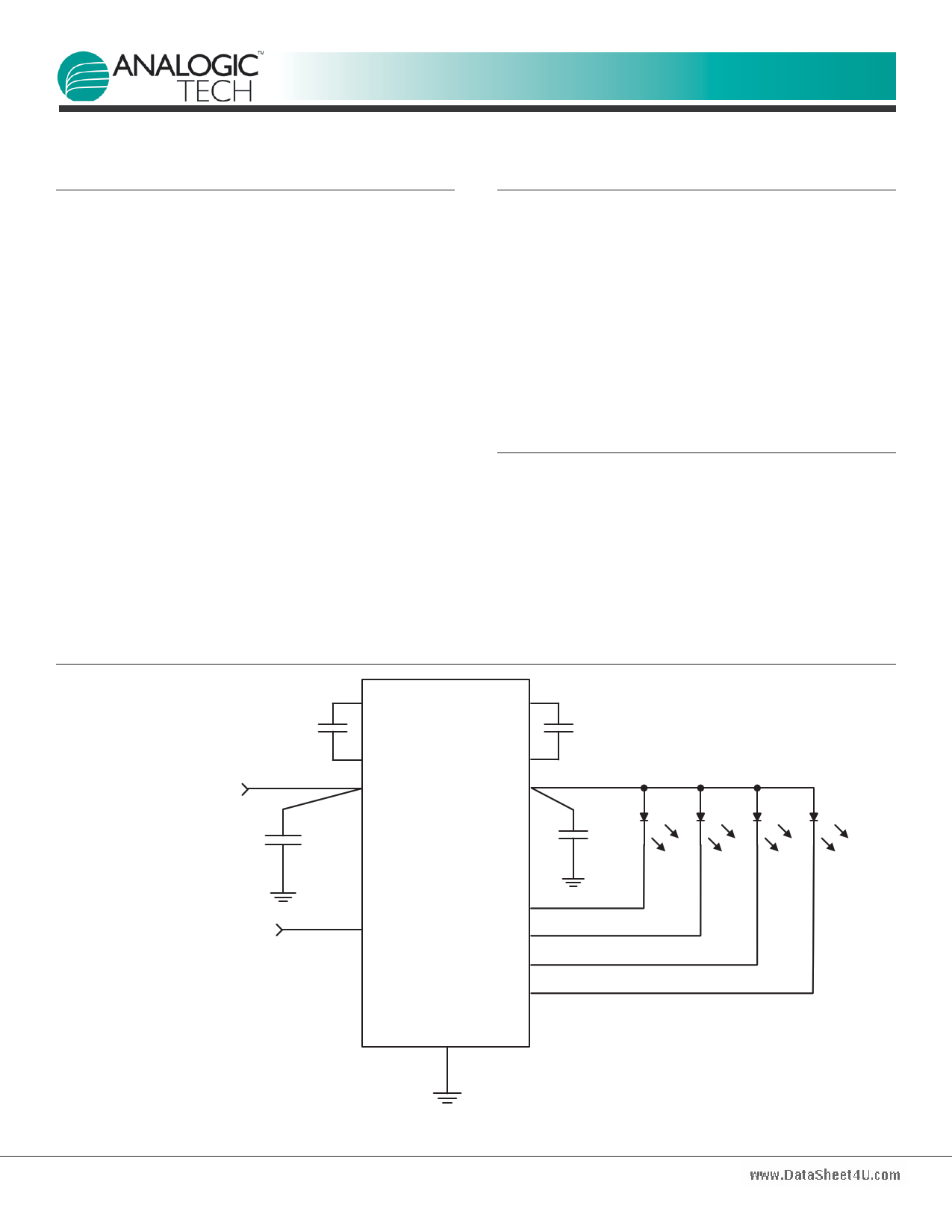
Typical Application
C1
1µF
VBATTERY
3.6V
C IN
1µF
EN/SET
S2Cwire Serial Control
C1+ C2+
C1- C2-
IN OUT
AAT3351
EN/SET
D1
D2
D3
D4
GND
C2
1µF
D1 D2 D3 D4
C OUT
1µF
3351.2009.02.1.0
www.analogictech.com
1
1 page 
www.DataSheet4U.com
ChargePumpTM
PRODUCT DATASHEET
AAT3351
High Efficiency 1x/1.5x Charge Pump
Typical Characteristics
VIN = 3.6V, CIN = COUT = C1 = C2 = 1μF; TA = 25°C, unless otherwise noted.
No Load Operating Current vs. Input Voltage
(1x Mode)
2.5
2.45
2.4
2.35
2.3
2.25
2.2 85°C
2.15 25°C
2.1 0°C
-40°C
2.05
2.7 3.1 3.5 3.9 4.3 4.7 5.1 5.5
Input Voltage (V)
No Load Operating Current vs. Input Voltage
(1.5x Mode)
8
7
6
5
4
3
85°C
2 25°C
1 0°C
-40°C
0
2.7 3.1 3.5 3.9 4.3 4.7 5.1 5.5
Input Voltage (V)
Backlight Current Matching vs. Temperature
(30mA/ch)
0.60
0.50
0.40
0.30
0.20
0.10
0.00
-40
-15 10 35 60
Temperature (°C)
85
Efficiency vs. Input Voltage
(DATA = 1, 30mA/ch)
100
VF = 3.3V
VF = 3.0V
85 VF = 2.7V
70
55
40
2.7 3.1 3.5 3.9 4.3 4.7 5.1 5.5
Input Voltage (V)
1.5x Output Voltage vs. Load Current
5.5
5
4.5
4
3.5 VIN = 3.3V
VIN = 3.6V
VIN = 4.2V
3
0 50 100 150 200
Load Current (mA)
1.5x Mode Operating Characteristics
(VIN = 3.3V; 30mA/ch Backlight, 1.5x Mode, COUT = 1µF)
VOUT
(AC coupled) 0
(50mV/div)
C1+
(2V/div)
C2+
(2V/div)
0
0
VIN
(AC coupled) 0
(20mV/div)
Time (1µs/div)
3351.2009.02.1.0
www.analogictech.com
5
5 Page 
www.DataSheet4U.com
ChargePumpTM
Capacitor Selection
Careful selection of the four external capacitors CIN, C1,
C2, and COUT is important because they will affect turn-on
time, output ripple, and transient load performance.
Optimum performance will be obtained when low equiva-
lent series resistance (ESR) ceramic capacitors are used.
In general, low ESR may be defined as less than 100mΩ.
A value of 1μF for all four capacitors is a good starting
point when choosing capacitors. If the LED current sinks
are only programmed for low current levels, then the
capacitor size may be decreased.
Capacitor Characteristics
Ceramic composition capacitors are highly recommended
over all other types of capacitors for use with the
AAT3351. Ceramic capacitors offer many advantages
over their tantalum and aluminum electrolytic counter-
parts. A ceramic capacitor has very low ESR, is lowest
cost, has a smaller PCB footprint, and is non-polarized.
Low ESR ceramic capacitors help to maximize charge
pump transient response. Since ceramic capacitors are
non-polarized, they are not prone to incorrect connec-
tion damage.
Equivalent Series Resistance
ESR is an important characteristic to consider when
selecting a capacitor. ESR is a resistance internal to a
capacitor that is caused by the leads, internal connec-
tions, size or area, material composition, and ambient
temperature. Capacitor ESR is typically measured in mil-
liohms for ceramic capacitors and can range to more
than several ohms for tantalum or aluminum electrolytic
capacitors.
PRODUCT DATASHEET
AAT3351
High Efficiency 1x/1.5x Charge Pump
Ceramic Capacitor Materials
Ceramic capacitors less than 0.1μF are typically made
from NPO or C0G materials. NPO and C0G materials
have tight tolerance and are stable over temperature.
Capacitors with large values are typically composed of
X7R, X5R, Z5U, or Y5V dielectric materials.
Large ceramic capacitors, greater than 2.2μF, are often
available in low-cost Y5V and Z5U dielectrics, but capac-
itors greater than 1μF are usually not required for
AAT3351 applications.
Capacitor area is another contributor to ESR. Capacitors
that are physically larger will have lower ESR when com-
pared to equivalent material but smaller capacitors.
These larger devices can improve circuit transient
response when compared to an equal value capacitor in
a smaller size.
Evaluation Board Layout
When designing a PCB for the AAT3351, the key require-
ments are:
1. Place two flying capacitors C1 and C2 as close to the
chip as possible; otherwise 1.5x mode performance
will be compromised.
2. Place input and output decoupling caps as close to
the chip as possible to reduce switching noise and
output ripple.
Manufacturer
Murata
AVX
TDK
Taiyo Yuden
Part Number
GRM219R71C104KA01
GRM188R61A105KA61
GRM219R61A475KE19
0603ZD105K
C1608X5R1E105K
C1608X5R1A475K
LMK107BJ475KA
Value (μF)
0.1
1
4.7
1
1
4.7
4.7
Voltage (V)
10
10
10
10
25
10
10
Table 2: Surface Mount Capacitors.
Temperature
Coefficient
X7R
X5R
X5R
X5R
X5R
X5R
X5R
Case
0805
0603
0805
0603
0603
0603
0603
3351.2009.02.1.0
www.analogictech.com
11
11 Page | ||
| Páginas | Total 15 Páginas | |
| PDF Descargar | [ Datasheet AAT3351.PDF ] | |
Hoja de datos destacado
| Número de pieza | Descripción | Fabricantes |
| AAT3351 | High Efficiency 1x/1.5x Charge Pump | Anadigics |
| Número de pieza | Descripción | Fabricantes |
| SLA6805M | High Voltage 3 phase Motor Driver IC. |
Sanken |
| SDC1742 | 12- and 14-Bit Hybrid Synchro / Resolver-to-Digital Converters. |
Analog Devices |
|
DataSheet.es es una pagina web que funciona como un repositorio de manuales o hoja de datos de muchos de los productos más populares, |
| DataSheet.es | 2020 | Privacy Policy | Contacto | Buscar |