|
|
|
PDF IR3721 Data sheet ( Hoja de datos )
| Número de pieza | IR3721 | |
| Descripción | Power Monitor IC | |
| Fabricantes | International Rectifier | |
| Logotipo | ||
Hay una vista previa y un enlace de descarga de IR3721 (archivo pdf) en la parte inferior de esta página. Total 16 Páginas | ||
|
No Preview Available !
www.datasheet4u.com
FEATURES
Accurate TruePowerTM monitor
• 2.5% static accuracy
• Minimizes dynamic errors
Minimizes power dissipation
• 5mV - 150mV full scale current range
Versatile
• Monitors power or current
• Single buck or multiphase converters
• Inductor DCR or resistive shunt sensing
Simple add-on to existing converters
10 pin 3x3 DFN lead free package
RoHS compliant
IR3721
DATA SHEET
Power Monitor IC with
Analog Output
DESCRIPTION
The IR3721 is a versatile power or current monitor IC
for low-voltage DC-DC converters. The IR3721
monitors the inductor current in buck or multiphase
converters using either a current sensing resistor or the
inductor’s winding resistance (DCR). The output (DI) is
a pulse code modulated signal whose duty ratio is
proportional to the inductor current. An analog voltage
that is proportional to power is realized by connecting
VK to VO and connecting an RC filter to DI.
The IR3721 uses Patent Pending TruePowerTM
technology to accurately capture highly dynamic power
waveforms typical of microprocessor loads.
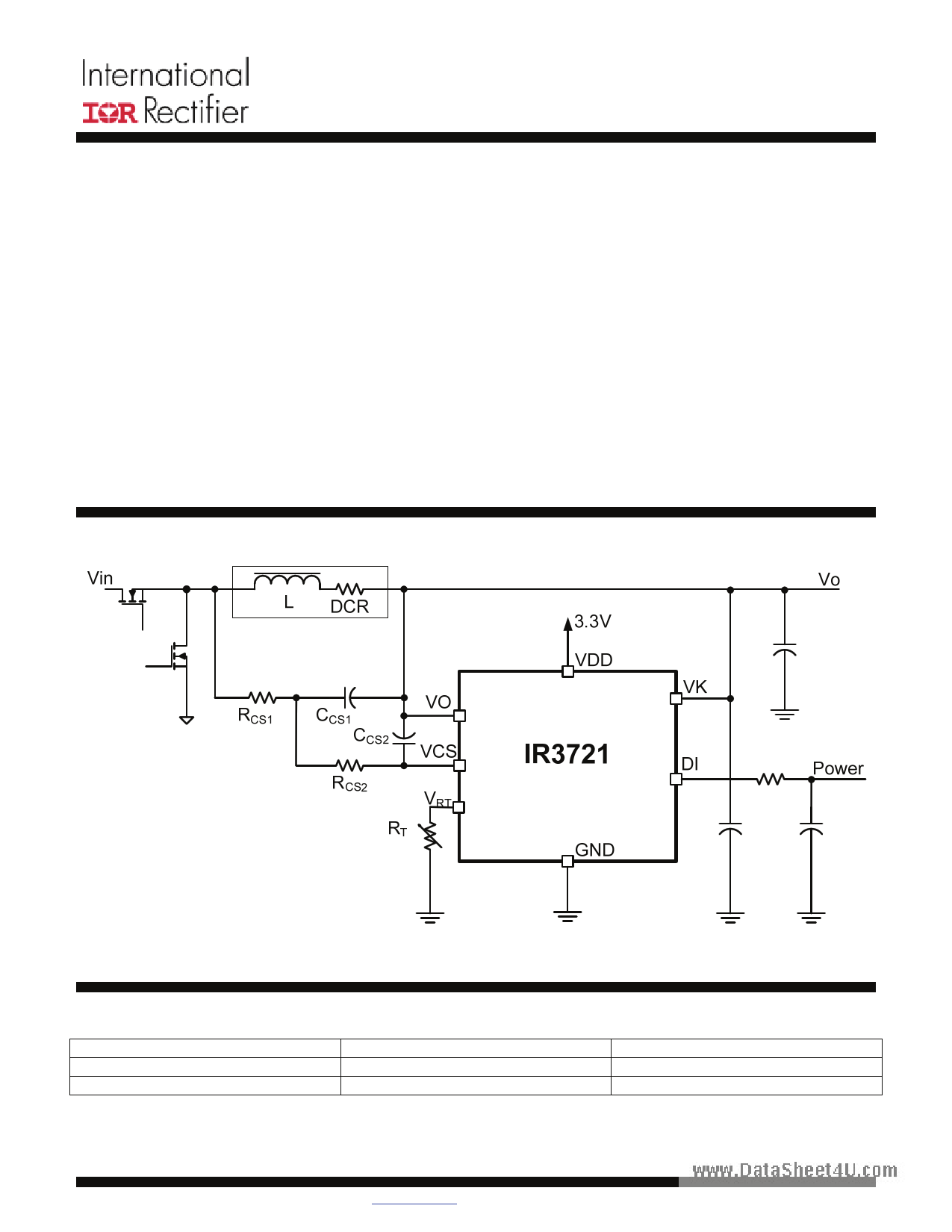
TYPICAL APPLICATION CIRCUIT
ORDERING INFORMATION
Device
IR3721MTRPBF
* IR3721MPBF
Package
10 lead DFN (3x3 mm body)
10 lead DFN (3x3 mm body)
* Samples only
Page 1 of 16
www.irf.com
Order Quantity
3000 piece reel
121 piece tube
07/14/08
1 page 
FUNCTIONAL DESCRIPTION
Please refer to the Functional Description Diagram
below. Power flow from the buck converter inductor is
www.dtahteaspheroetd4uuc.ctoomf output voltage times the current IL
flowing through the inductor.
Power is measured with the aid of International
Rectifier’s proprietary TruePower™ circuit. Current is
converted to a duty ratio that appears at the DI pin.
The duty ratio of the DI pin is
DIDUTYRATIO
=
(R
IL ⋅
CS1
DCR
+ RCS2
)
⋅
RT
VRΤ
Equation 1
IR3721
DATA SHEET
The amplitude of the DI pin is the voltage appearing
at pin VK. If a fixed voltage is applied to VK then the
output of the RC filter driven by DI will be proportional
to inductor current IL.
If VO is applied to VK as shown in the figure then the
output of the DI driven RC network will be
proportional to power. The full-scale voltage that can
be measured is established on the chip to be 1.8V.
The full scale power PFS that can be measured is the
product of full-scale voltage and full scale current.
The full-scale current that can be measured
corresponds to a duty ratio of one.
IL
Vin
L DCR
RCS1
CCS1
CCS2
RCS2
VO
VCS
VRT
RT
VDD
VK
Vo
IR3721 DI Power
GND
Figure 1 Functional Description Diagram
Page 5 of 16
www.irf.com
07/14/08
5 Page 
IR3721
DATA SHEET
LAYOUT GUIDELINES
Refer to figures 7 through 11 for guidance laying out
the IR3721. These guidelines also apply to resistive
www.dcautarsrehenett4sue.ncosming. The following guidelines will
minimize sources of noise and error, which is
required because millivolt level signals correspond to
amps of inductor current.
1. Place the capacitor Ccs2 close to the VO and
VCS pins of the IR3721. Treat VO and VCS as a
differential signal pair back to the IC as shown in
the elliptical area designated #1 of figure 8.
2. Sense the inductor (or shunt) Kelvin style at its
terminals. Route the leads back as a differential
pair. Refer to area #2 of figure 8.
3. Route signal VOUT back to the IC VK pin on its
own dedicated trace. Refer to area #3 of figure 8.
4. Place the thermistor near the inductor. Refer to
area #4 of figure 8. Route the thermistor leads
back to the rest of the network using differential
traces. Mount the rest of the thermistor network
consisting of Rs, Rp, and R1 close to the IC.
1 L1
2
5. Use an isolated dedicated ground plane
connected only to components associated with
the IR3721 that connect to GND as shown in
figure 9. Connect this dedicated ground plane at
one location only to the ground of the monitored
voltage. The thermally relived via in figure eight
illustrates this connection.
6. Bypass IC VDD pin 5 to GND pin 4 with a high
quality 0.1 μF ceramic capacitor. Refer to area #6
of figure 8.
7. Bypass the IC VK pin to GND with a high quality
0.1 μF ceramic capacitor. Refer to area #7 of
figure 8.
VOUT
Rcs1
Ccs1
Rcs2
Ccs2
Rs
U1
1
2
3
4
5
CS VCC_1
VO VK
RT DI
GND_1GND_3
VCC GND_4
10
9
8
7
6
IR3721
R_DI_FILT
VOUT
DI_FILT
VDD
Rth
Rp
R1
C_VDD
0.1uF
C_VK
0.1uF
C_DI_FILT
Figure 7 Example schematic
0
GND
Page 11 of 16
www.irf.com
07/14/08
11 Page | ||
| Páginas | Total 16 Páginas | |
| PDF Descargar | [ Datasheet IR3721.PDF ] | |
Hoja de datos destacado
| Número de pieza | Descripción | Fabricantes |
| IR3720 | Power Monitor IC | International Rectifier |
| IR3721 | Power Monitor IC | International Rectifier |
| IR3725 | Input Power Monitor IC | International Rectifier |
| Número de pieza | Descripción | Fabricantes |
| SLA6805M | High Voltage 3 phase Motor Driver IC. |
Sanken |
| SDC1742 | 12- and 14-Bit Hybrid Synchro / Resolver-to-Digital Converters. |
Analog Devices |
|
DataSheet.es es una pagina web que funciona como un repositorio de manuales o hoja de datos de muchos de los productos más populares, |
| DataSheet.es | 2020 | Privacy Policy | Contacto | Buscar |