|
|
|
PDF T0810 Data sheet ( Hoja de datos )
| Número de pieza | T0810 | |
| Descripción | 3-channel Laser Driver | |
| Fabricantes | ATMEL Corporation | |
| Logotipo | ||
Hay una vista previa y un enlace de descarga de T0810 (archivo pdf) en la parte inferior de esta página. Total 9 Páginas | ||
|
No Preview Available !
T0810
3-Channel Laser Driver with RF Osc. and APC Amplifier
Description
www.datashTeehte4uT.c0o8m10 is a laser diode driver for the operation of a
grounded laser diode for CD-RW drives. It includes three
channels for three different optical power levels which
are controlled by a separate IC. The read channel gener-
ates a continuous output level whereas the channels 2 and
3 are provided as write channels with very fast switching
speeds. Write current pulses are enabled when a ‘low’
signal is applied to the NE Pins. All channels are summed
together at the IOUT Pin. Each channel can contribute up
to 150 mA to the total output current of up to 200 mA. A
total gain of 400 mA is provided between each reference
current input and output. Although the reference inputs
are current inputs, voltage control is possible by using
external resistors.
An on-chip RF oscillator is provided to reduce laser mode
hopping noise during read mode. Frequency and swing
can be set by two external resistors. Oscillation is enabled
by a ‘high’ at the ENOSC Pin. Complete output current
and oscillator switch-off is achieved by a ‘low’ at the
ENABLE input.
The T0810 also includes a fast settling APC (Adaptive
Power Control) transimpedance amplifier. It is provided
to interface between the front end monitor photo diode
and the ALPC (Adaptive Laser Diode Power Controller)
circuit.
Electrostatic sensitive device.
Observe precautions for handling.
Features
D Current-controlled output current source with 3 input
channels
D Low-power consumption
D Output current per channel to 150 mA
D Total output current to 200 mA
D Rise time 1.0 ns / fall time 1.1 ns
D On-chip RF oscillator
D Control of frequency and swing by use of 2 external
resistors
D Oscillator frequency range from 200MHz to 500 MHz
D Oscillator swing to 100 mA
D Fast settling APC amplifier
D Single 5-V power supply
D Common enable / disable input
D TTL/CMOS control signals
D Small SSO16 package
Application
D CD-RW drives
D Writable optical drives
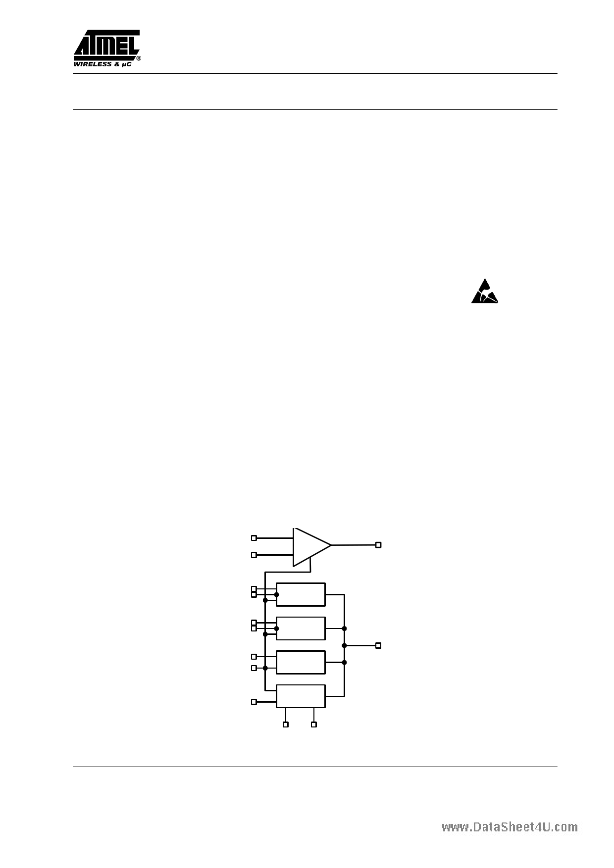
Block Diagram
PDIN
VREF
APC
VOUT
I3
NE3 Channel 3
I2
NE2 Channel 2
IR
ENABLE
Read
channel
ENOSC
RF oscillator
RF RS
Figure 1. Block diagram
IOUT
Rev. A5, 08-Aug-01
1 (9)
1 page 
T0810
Electrical Characteristics :
Laser Current Amplifier Outputs AC Performance
VCC = + 5 V, IOUT = 40 mA DC with 40 mA pulse, TA = 25°C unless otherwise specified
www.datasheet4u.com Parameter
Test Conditions / Pins
Symbol Min. Typ.
Max.
Unit
Write rise time
Write fall time
Output current overshoot
IOUT ON propagation delay
IOFF OFF propagation delay
Disable time
Enable time
Amplifier bandwidth
Oscillator
Oscillator frequency
Osc. temperature coefficient
Disable time oscillator
Enable time oscillator
IOUT = 40 mA (read) + 40 mA
(10% to 90%) 1)
IOUT = 40 mA (read) + 40 mA
(10% to 90%) 1)
IOUT = 40 mA (read) + 40 mA 1)
NE 50% High–Low to IOUT at
50% of final value
NE 50% Low–High to IOUT at
50% of final value
ENABLE 50% High–Low to
IOUT at 50% of final value
ENABLE 50% Low–High to
IOUT at 50% of final value
IOUT = 50 mA, all channels,
–3dB value
tRISE
tFALL
OS
tON
tOFF
tDIS
tEN
BWLCA
RF = 4.3 kΩ
RF = 4.3 kΩ
ENOSC 50% High–Low to IOUT
at 50% of final value
ENOSC 50% Low–High to IOUT
at 50% of final value
FOSC
TCOSC
TDISO
TENO
380
1.0
1.4
5
2.0
2.0
10
50
16
470
–150
4
2
3.0 ns
3.0 ns
%
ns
ns
ns
ns
MHz
560 MHz
ppm/°C
ns
ns
1) Load resistor at IOUT: 10 Ω // 39 Ω + 50 Ω (see test circuit)
Electrical Characteristics : APC Amplifier
VCC = 5 V, TA = 25°C, RLOAD = 2 kΩ to VREF unless otherwise specified
Parameter
Test Conditions / Pins Symbol Min.
Typ.
Max.
Unit
Bandwidth
Slew rate
Setting time
Open loop voltage gain
Offset voltage
Input bias current
Common mode input range
G = 1, Cload = 22 pF
G = 1, VOUT = 1 V to 3 V
To 0.1%, VOUT = 1 V to 3 V
VOUT = 1 V to 3 V
VREF = 3 V
VREF = 3 V
CMRR > = 54 dB
BWAPC
SR
ts
Avol
VOS
CMIR
Common mode rejection ratio VCM = 0.5 V to 3.0 V
Input impedance
Input capacitance
Pin 16 (PDIN)
Output voltage swing
RL = 2 kΩ to VREF
CMRR
RIN
CIN
VOUT
–5
1
1
200 MHz
80 V/µs
50 ns
60 dB
+5 mV
–1.5 µA
VCC–1.5 V
60 dB
20 kΩ
2 pF
VCC–1.5 V
Rev. A5, 08-Aug-01
5 (9)
5 Page | ||
| Páginas | Total 9 Páginas | |
| PDF Descargar | [ Datasheet T0810.PDF ] | |
Hoja de datos destacado
| Número de pieza | Descripción | Fabricantes |
| T0810 | 3-channel Laser Driver | ATMEL Corporation |
| T0810xH | (T0810xH / T0812xH) Standard Triacs | SGS-Thomson |
| T0812xH | (T0810xH / T0812xH) Standard Triacs | SGS-Thomson |
| Número de pieza | Descripción | Fabricantes |
| SLA6805M | High Voltage 3 phase Motor Driver IC. |
Sanken |
| SDC1742 | 12- and 14-Bit Hybrid Synchro / Resolver-to-Digital Converters. |
Analog Devices |
|
DataSheet.es es una pagina web que funciona como un repositorio de manuales o hoja de datos de muchos de los productos más populares, |
| DataSheet.es | 2020 | Privacy Policy | Contacto | Buscar |