|
|
|
PDF XC9201 Data sheet ( Hoja de datos )
| Número de pieza | XC9201 | |
| Descripción | PWM Controlled Step-Down DC/DC Converters | |
| Fabricantes | Torex Semiconductor | |
| Logotipo | ||
Hay una vista previa y un enlace de descarga de XC9201 (archivo pdf) en la parte inferior de esta página. Total 24 Páginas | ||
|
No Preview Available !
XC9201 Series
PWM Controlled Step-Down DC/DC Controllers
ETR0502_004
■GENERAL DESCRIPTION
The XC9201 series are step-down multiple current and voltage feedback DC/DC controller ICs. Current sense, clock
frequencies and amp feedback gain can all be externally regulated.
A stable power supply is possible with output currents of up to 3.0A. With output voltage fixed internally, output voltage is
selectable in 100mV increments (semi-custom) within a 1.2V ~ 16.0V range. (±2.5%).
For output voltages outside this range, we recommend the FB version which has a 0.9V internal reference voltage. Using this
version, the required output voltage can be set-up using 2 external resistors.
Switching frequencies can also be set-up externally within a range of 100kHz~600kHz and therefore frequencies suited to
your particular application can be selected.
With the current sense function, peak currents (which flow through the driver transistor and the coil) can be controlled.
Soft-start time can be adjusted using external resistors and capacitors.
During shutdown (CE pin =L), consumption current can be reduced to as little as 0.5μA (TYP.) or less and with U.V.L.O.
(Under Voltage Lock Out) built-in, the external transistor will be automatically shut off below the regulated voltage.
■APPLICATIONS
●Mobile, Cordless phones
●Palm top computers, PDAs
●Portable games
●Cameras, Digital cameras
●Notebook computers
■FEATURES
Stable Operations via Current & Voltage Multiple
Feedback
Unlimited Options for Peripheral Selection
Current Protection Circuit
Ceramic Capacitor Compatible
Input Voltage Range
: 2.5V ~20V
Output Voltage Range
: 1.2V ~ 16V
Oscillation Frequency Range : 100kHz ~ 600kHz
Output Current
: Up To 3.0A
Package
: MSOP-8A
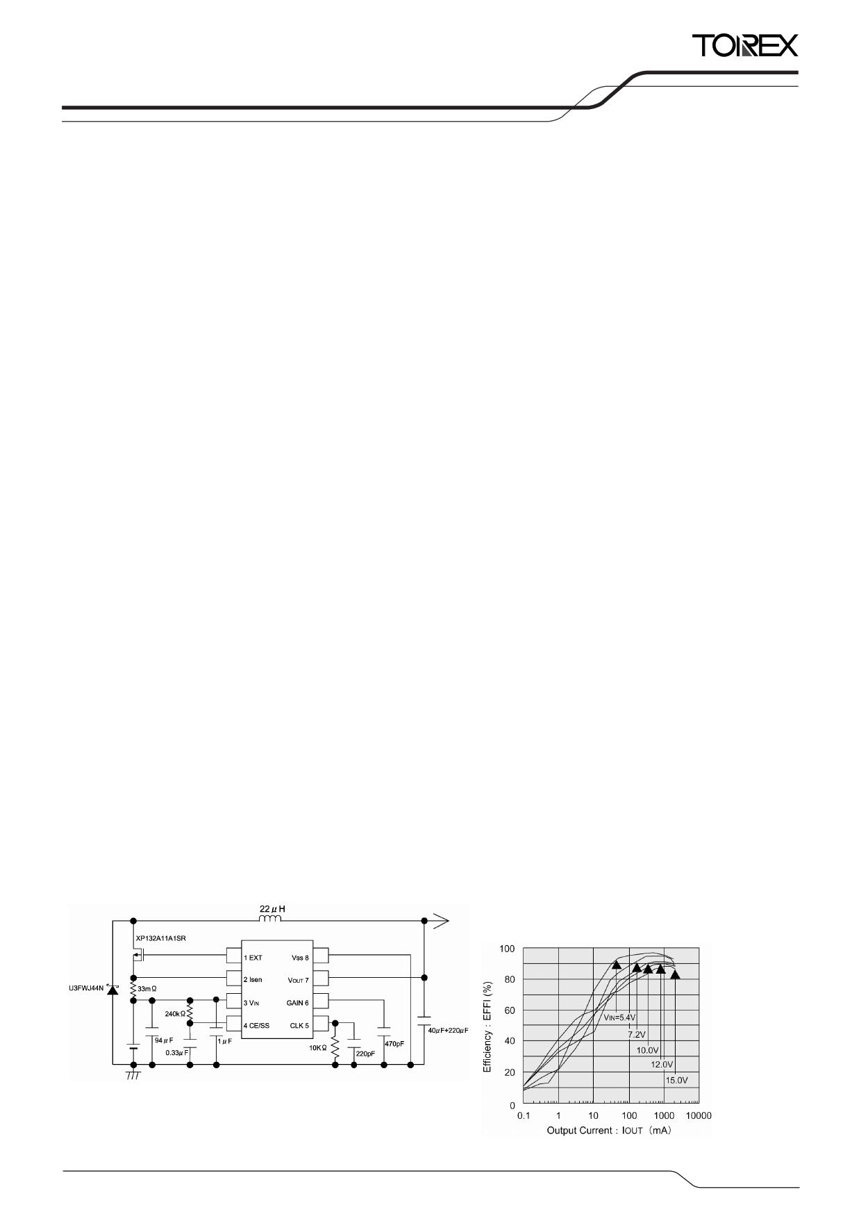
■TYPICAL APPLICATION CIRCUIT
■TYPICAL PERFORMANCE
CHARACTERISTICS
VOUT:5.0V FOSC:330kHz
1/24
1 page 
XC9201
Series
■ELECTRICAL CHARACTERISTICS (Continued)
XC9201C33AKR
PARAMETER
SYMBOL
Output Voltage
VOUT
Maximum
Operating Voltage
VINmax
Minimum
Operating Voltage
VINmin
U.V.L.O. Voltage
VUVLO
Supply Current 1
IDD1
Supply Current 2
IDD2
Stand-by Current
ISTB
CLK
Oscillation Frequency
FOSC
Frequency Input Stability
ΔFOSC
ΔVIN・FOSC
Frequency
ΔFOSC
Temperature Fluctuation ΔTOPR・FOSC
Maximum Duty Cycle MAXDTY
Minimum Duty Cycle
MINDTY
Current Limiter Voltage
ILIM
ISEN Current
IISEN
CE "High" Current
ICEH
CE "Low" Current
ICEL
CE "High" Voltage
VCEH
CE "Low" Voltage
EXT "High"
ON Resistance
EXT "Low"
ON Resistance
Efficiency (*2)
Soft-start Time
CC/GAIN Pin
Output Impedance
VCEL
REXTH
REXTL
EFFI
TSS
RCCGAIN
CONDITIONS
IOUT=300mA
EXT voltage = High
VIN=5.0V, CE=VIN=VOUT
VIN=20.0V, CE=VIN, VOUT=VSS
VIN=5.0V, CE=VOUT=VSS
RT=10.0kΩ, CT=220pF
VIN=2.5V~20V
VIN=5.0V
Topr=-40~+85℃
VOUT=VSS
VOUT=VIN
VIN pin voltage - ISEN pin voltage
VIN=5.0V, ISEN=5.0V
CE=VIN=20.0V, VOUT=0V
CE=0V, VIN=20.0V, VOUT=0V
CLK Oscillation start,
VOUT=0V, CE:Voltage applied
CLK Oscillation stop,
VOUT=0V, CE:Voltage applied
EXT=VIN-0.4V,
CE=VOUT=VIN (*1)
EXT=0.4V, CE=VIN,
VOUT=Vss (*1)
Connect CSS and RSS,
CE : 0V→5.0V
MIN.
3.218
20
-
1.0
-
-
-
280
-
-
100
-
90
4.5
-0.1
-0.1
0.6
-
-
-
-
5
-
TYP.
3.300
-
-
1.4
115
130
0.5
330
±5
±5
-
-
150
7
0
0
-
-
24
22
93
10
400
MAX. UNITS
3.382 V
-V
2.200
2.0
220
235
2.0
380
V
V
μA
μA
μA
kHz
-%
-%
-%
0%
220 mV
13 μA
0.1 μA
0.1 μA
-V
0.2 V
33 Ω
31 Ω
-%
20 ms
- kΩ
Ta=25℃
CIRCUITS
①
①
①
⑤
②
②
②
③
③
③
④
④
⑥
⑥
⑤
⑤
⑤
⑤
④
④
①
①
⑦
Unless otherwise stated, VIN=5.0V
NOTE:
*1: On resistance = 0.4V / measurement current
*2: EFFI = {[(output voltage) x (output current)] / [(input voltage) x (input current)]} x 100
*3: The capacity range of the condenser used to set the external CLK frequency is 180 ~ 300pF
5/24
5 Page 
XC9201
Series
■OPERATIONAL EXPLANATION (Continued)
●Functional Settings
1. Soft-Start
CE and soft-start (SS) functions are commonly assigned to the CE/SS pin. The soft start function is effective until the
voltage at the CE pin reaches approximately 1.55V rising from 0V. Soft start time is approximated by the equation below
according to values of Vcont, RSS, and CSS.
T=-Css x Rss x ln((Vcont-1.55)/Vcont)
Example: When Css=0.1μF, Rss=470kΩ, and Vcont=5V, T= - 0.1 x 10-6 × 470 x 103 × In((5-1.55) / 5)=17.44ms.
Set the soft-start time to a value sufficiently longer than the period of a clock pulse.
> Circuit example 1: N-ch open drain
> Circuit example 2: CMOS logic (low current dissipation)
> Circuit example 3: CMOS logic (low current dissipation)
11/24
11 Page | ||
| Páginas | Total 24 Páginas | |
| PDF Descargar | [ Datasheet XC9201.PDF ] | |
Hoja de datos destacado
| Número de pieza | Descripción | Fabricantes |
| XC9201 | PWM Controlled Step-Down DC/DC Converters | Torex Semiconductor |
| XC9206 | (XC9206 - XC9208) PWM/PFM Switchable Step-Down DC/DC Converters | Torex Semiconductor |
| XC9207 | (XC9206 - XC9208) PWM/PFM Switchable Step-Down DC/DC Converters | Torex Semiconductor |
| XC9208 | (XC9206 - XC9208) PWM/PFM Switchable Step-Down DC/DC Converters | Torex Semiconductor |
| Número de pieza | Descripción | Fabricantes |
| SLA6805M | High Voltage 3 phase Motor Driver IC. |
Sanken |
| SDC1742 | 12- and 14-Bit Hybrid Synchro / Resolver-to-Digital Converters. |
Analog Devices |
|
DataSheet.es es una pagina web que funciona como un repositorio de manuales o hoja de datos de muchos de los productos más populares, |
| DataSheet.es | 2020 | Privacy Policy | Contacto | Buscar |