|
|
|
PDF LM1812 Data sheet ( Hoja de datos )
| Número de pieza | LM1812 | |
| Descripción | ULTRASONIC TRANSCEIVER | |
| Fabricantes | National Semiconductor | |
| Logotipo | ||
Hay una vista previa y un enlace de descarga de LM1812 (archivo pdf) en la parte inferior de esta página. Total 10 Páginas | ||
|
No Preview Available !
April 1989
LM1812 Ultrasonic Transceiver
General Description
The LM1812 is a general purpose ultrasonic transceiver de-
signed for use in a variety of ranging sensing and commu-
nications applications The chip contains a pulse-modulated
class C transmitter a high gain receiver a pulse modulation
detector and noise rejection circuitry
A single LC network defines the operating frequency for
both the transmitter and receiver The class C transmitter
output drives up to 1A (12W) peak at frequencies up to
325 kHz The externally programmed receiver gain provides
a detection sensitivity of 200 mVp-p Detection circuitry in-
cluded on-chip is capable of rejecting impulse noise with
external programming The detector output sinks up to 1A
Applications include sonar systems non-contact ranging
and acoustical data links in both liquid and gas ambients
Features
Y One or two-transducer operation
Y Transducers interchangeable without realignment
Y No external transistors
Y Impulse noise rejection
Y No heat sinking
Y Protection circuitry included
Y Detector output drives 1A peak load
Y Ranges in excess of 100 feet in water 20 feet in air
Y 12W peak transmit power
Applications
Y Liquid level measurement
Y Sonar
Y Surface profiling
Y Data links
Y Hydroacoustic communications
Y Non-contact sensing
Y Industrial process control
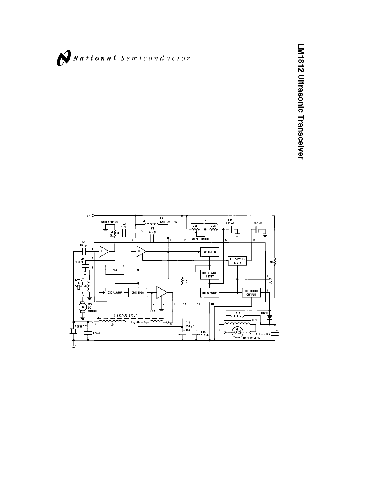
Typical Application
Order Number LM1812N
See NS Package Number N18A
TL H 7892 – 1
Note Echo returns are displayed by a neon lamp on a motor driven disc Connections to the neon are made through brushes and slip rings Rotating with
and counterbalancing the neon lamp is a permanent magnet whose field induces a pulse in a stationary coil (L8) as it passes by This pulse keys the
LM1812’s transmitter
Available from Toko America 1250 Feehanville Drive Mount Prospect Illinois 60056 Tel (312) 297-0070
Available from Massa Products Corporation 280 Lincoln Street Hingham Massachusetts 02043 Tel (617) 749-4800
FIGURE 1 200 kHz Depth Sounder 5 Feet to 100 Feet
C1995 National Semiconductor Corporation TL H 7892
RRD-B30M115 Printed in U S A
1 page 
Application Hints (Continued)
Where additional power is desired a pulse amplifier or a
pulse stretcher can be used as shown in Figure 7 The pulse
amplifier (Figure 7a ) increases output current up to 5A The
pulse stretcher (Figure 7b ) increases output current and
pulse width The wider pulse of Figure 7b is especially useful
at lower frequencies where the relatively narrow 1 ms pulse
creates a large peak current demand for a given power lev-
el Pulse width as a function of R is plotted in Figure 8
Pin 8 performs the function of switching the LM1812 into
either the transmit or receive mode When pin 8 is held high
the chip is in the transmit mode When held low it is in the
receive mode The input current at pin 8 should be designed
to operate within a 1 mA–10 mA range
RECEIVER
The receiver section (Figure 9 ) contains two separate gain
stages
In some applications large voltages are applied across the
transducer during transmit Since the receiver input is cou-
pled to the transducer some protection is necessary to limit
the input current spikes to less than 50 mA Where the volt-
age across the transducer is less than 200 Vp-p a C4 reac-
tance of 5 kX at the operating frequency is adequate pro-
tection Above 200 Vp-p a 5 kX resistor should be inserted
in series with C4
Since the L1-C1 tank circuit is shared with the oscillator
both the transmitter and receiver are always tuned to the
same frequency The second stage voltage gain is given by
0Q L1
AV e 70 C1
(4)
where Q e unloaded Q of L1-C1 tank
When the LM1812 is in the transmit mode the second gain
stage is turned OFF When switching back to the receive
mode the gain stage does not turn ON immediately but
instead turns ON after a slight delay as programmed by C9
This delay blanks the receiver (and therefore the detector)
momentarily giving the transducer time to stop ringing
FIGURE 7a Pulse Amplifier
TL H 7892 – 7
FIGURE 7b Pulse Stretcher
TL H 7892 – 8
TL H 7892–9
FIGURE 8 Pulse Stretcher
Resistance vs Pulse Width
AV e 24 dB
FIGURE 9 Receiver Section
TL H 7892 – 10
5
5 Page | ||
| Páginas | Total 10 Páginas | |
| PDF Descargar | [ Datasheet LM1812.PDF ] | |
Hoja de datos destacado
| Número de pieza | Descripción | Fabricantes |
| LM1812 | ULTRASONIC TRANSCEIVER | National Semiconductor |
| LM1815 | Adaptive Variable Reluctance Sensor Amplifier | National Semiconductor |
| LM1815 | LM1815 Adaptive Variable Reluctance Sensor Amplifier (Rev. F) | Texas Instruments |
| LM1815EP | LM1815EP Enhanced Plastic Adaptive Variable Reluctance Sensor Amplifier (Rev. B) | Texas Instruments |
| Número de pieza | Descripción | Fabricantes |
| SLA6805M | High Voltage 3 phase Motor Driver IC. |
Sanken |
| SDC1742 | 12- and 14-Bit Hybrid Synchro / Resolver-to-Digital Converters. |
Analog Devices |
|
DataSheet.es es una pagina web que funciona como un repositorio de manuales o hoja de datos de muchos de los productos más populares, |
| DataSheet.es | 2020 | Privacy Policy | Contacto | Buscar |