|
|
|
PDF IRF6623PBF Data sheet ( Hoja de datos )
| Número de pieza | IRF6623PBF | |
| Descripción | HEXFET Power MOSFET | |
| Fabricantes | International Rectifier | |
| Logotipo | ||
Hay una vista previa y un enlace de descarga de IRF6623PBF (archivo pdf) en la parte inferior de esta página. Total 9 Páginas | ||
|
No Preview Available !
l RoHS Compliant
l Lead-Free (Qualified up to 260°C Reflow)
wwlwA.dpatpalsichaeetito4un.cSopmecific MOSFETs
l Ideal for CPU Core DC-DC Converters
l Low Conduction Losses
l High Cdv/dt Immunity
l Low Profile (<0.7mm)
l Dual Sided Cooling Compatible
l Compatible with existing Surface Mount Techniques
PD - 97085
IRF6623PbF
IRF6623TRPbF
DirectFET Power MOSFET
VDSS
20V
RDS(on) max
5.7mΩ@VGS = 10V
9.7mΩ@VGS = 4.5V
Qg(typ.)
11nC
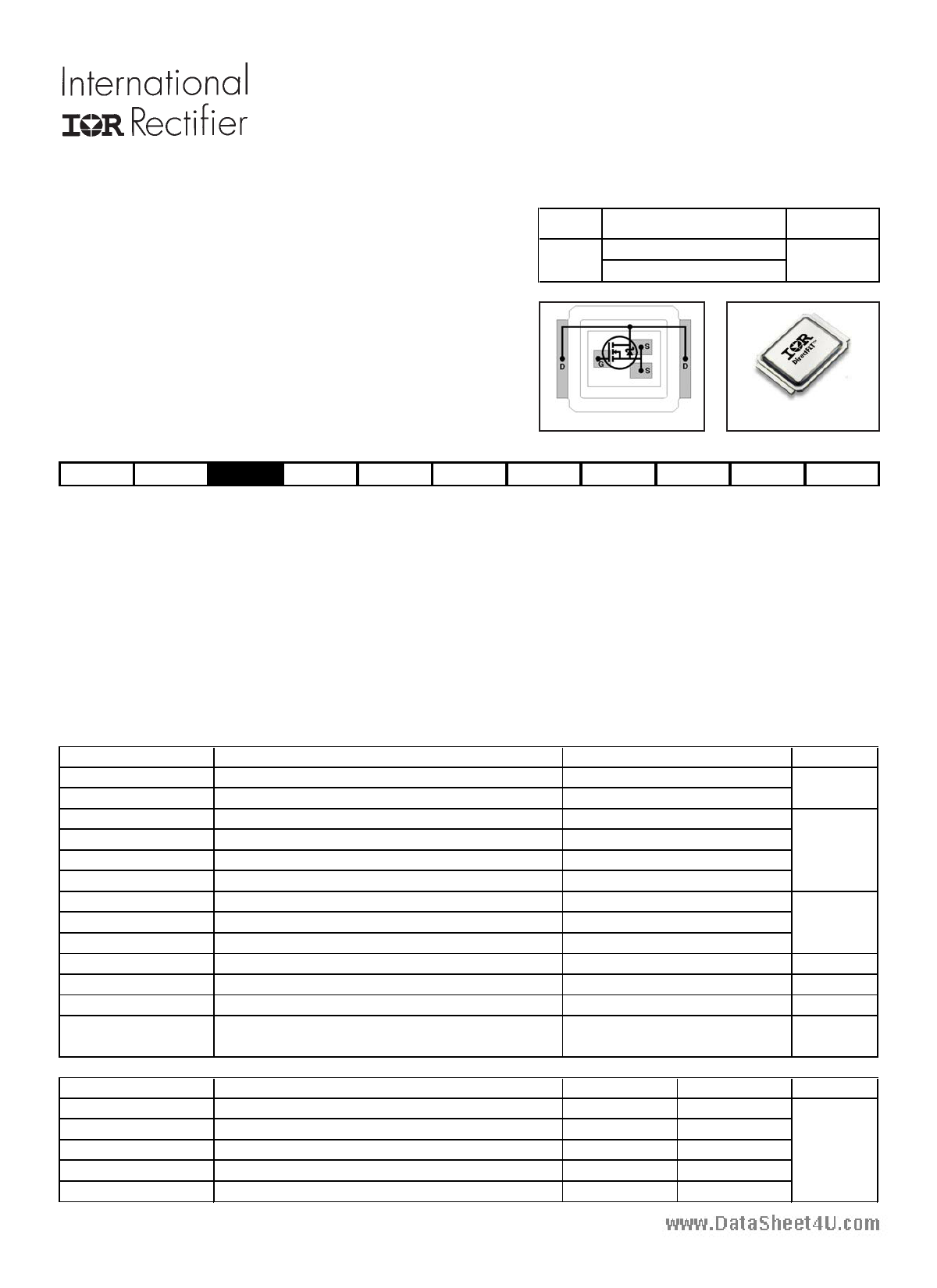
Applicable DirectFET Outline and Substrate Outline (see p.8,9 for details)
ST
DirectFET ISOMETRIC
SQ SX ST
MQ MX MT
Description
The IRF6623PbF combines the latest HEXFET® Power MOSFET Silicon technology with the advanced DirectFETTM packag-
ing to achieve the lowest on-state resistance in a package that has the footprint of a MICRO-8 and only 0.7 mm profile. The
DirectFET package is compatible with existing layout geometries used in power applications, PCB assembly equipment and
vapor phase, infra-red or convection soldering techniques, when application note AN-1035 is followed regarding the manufac-
turing methods and processes. The DirectFET package allows dual sided cooling to maximize thermal transfer in power
systems, improving previous best thermal resistance by 80%.
The IRF6623PbF balances both low resistance and low charge along with ultra low package inductance to reduce both
conduction and switching losses. The reduced total losses make this product ideal for high efficiency DC-DC converters that
power the latest generation of processors operating at higher frequencies. The IRF6623PbF has been optimized for param-
eters that are critical in synchronous buck operating from 12 volt bus converters including Rds(on) and gate charge to
minimize losses in the control FET socket.
Absolute Maximum Ratings
Parameter
Max.
Units
VDS
VGS
ID @ TC = 25°C
ID @ TA = 25°C
ID @ TA = 70°C
IDM
PD @TC = 25°C
PD @TA = 25°C
PD @TA = 70°C
EAS
IAR
Drain-to-Source Voltage
Gate-to-Source Voltage
iContinuous Drain Current, VGS @ 10V
ÃfContinuous Drain Current, VGS @ 10V
fContinuous Drain Current, VGS @ 10V
Pulsed Drain Current
iPower Dissipation
fPower Dissipation
fPower Dissipation
dSingle Pulse Avalanche Energy
ÃAvalanche Current
Linear Derating Factor
20
±20
55
16
13
120
42
1.4
2.1
43
40
0.017
V
A
W
mJ
A
W/°C
TJ Operating Junction and
TSTG
Storage Temperature Range
Thermal Resistance
-40 to + 150
°C
RθJA
RθJA
RθJA
RθJC
RθJ-PCB
Parameter
fjJunction-to-Ambient
gjJunction-to-Ambient
hjJunction-to-Ambient
ijJunction-to-Case
Junction-to-PCB Mounted
Typ.
–––
12.5
20
–––
1.0
Max.
58
–––
–––
3.0
–––
Units
°C/W
Notes through are on page 2
www.irf.com
1
5/3/06
1 page 
20
ID = 15A
16
www.da1ta2sheet4u.com
8
4
2.0
TJ = 125°C
TJ = 25°C
4.0 6.0 8.0
VGS, Gate-to-Source Voltage (V)
10.0
Fig 12. On-Resistance Vs. Gate Voltage
15V
IRF6623PbF
200
ID
TOP 5.2A
160 7.9A
BOTTOM 12A
120
80
40
0
25
50 75 100 125
Starting TJ, Junction Temperature (°C)
150
Fig 13. Maximum Avalanche Energy Vs. Drain Current
V(BR)DSS
tp
VDS
L
DRIVER
RG
2V0GVS
tp
D.U.T
IAS
0.01Ω
+
-
VDD A
Fig 14a. Unclamped Inductive Test Circuit
VDS
LD
+
VDD -
VGS
Pulse Width < 1µs
Duty Factor < 0.1%
D.U.T
Fig 15a. Switching Time Test Circuit
L
VCC
DUT
0
1K
IAS
Fig 14b. Unclamped Inductive Waveforms
VDS
90%
10%
VGS
td(on) tr
td(off) tf
Fig 15b. Switching Time Waveforms
Id
Vds
Vgs
Vgs(th)
Fig 16a. Gate Charge Test Circuit
www.irf.com
Qgs1 Qgs2 Qgd
Qgodr
Fig 16b. Gate Charge Waveform
5
5 Page | ||
| Páginas | Total 9 Páginas | |
| PDF Descargar | [ Datasheet IRF6623PBF.PDF ] | |
Hoja de datos destacado
| Número de pieza | Descripción | Fabricantes |
| IRF6623PBF | HEXFET Power MOSFET | International Rectifier |
| Número de pieza | Descripción | Fabricantes |
| SLA6805M | High Voltage 3 phase Motor Driver IC. |
Sanken |
| SDC1742 | 12- and 14-Bit Hybrid Synchro / Resolver-to-Digital Converters. |
Analog Devices |
|
DataSheet.es es una pagina web que funciona como un repositorio de manuales o hoja de datos de muchos de los productos más populares, |
| DataSheet.es | 2020 | Privacy Policy | Contacto | Buscar |