|
|
|
PDF L6226Q Data sheet ( Hoja de datos )
| Número de pieza | L6226Q | |
| Descripción | DMOS dual full bridge driver | |
| Fabricantes | STMicroelectronics | |
| Logotipo | ||
Hay una vista previa y un enlace de descarga de L6226Q (archivo pdf) en la parte inferior de esta página. Total 28 Páginas | ||
|
No Preview Available !
L6226Q
DMOS dual full bridge driver
Features
■ Operating supply voltage from 8 to 52 V
www.DataSheet4U■.com2.8 A output peak current (1.4 A DC)
■ RDS(on) 0.73 Ω typ. value @ TJ = 25 °C
■ Operating frequency up to 100 kHz
■ Programmable high side overcurrent detection
and protection
■ Diagnostic output
■ Paralleled operation
■ Cross conduction protection
■ Thermal shutdown
■ Under voltage lockout
■ Integrated fast free wheeling diodes
Applications
■ Bipolar stepper motor
■ Dual or quad DC motor
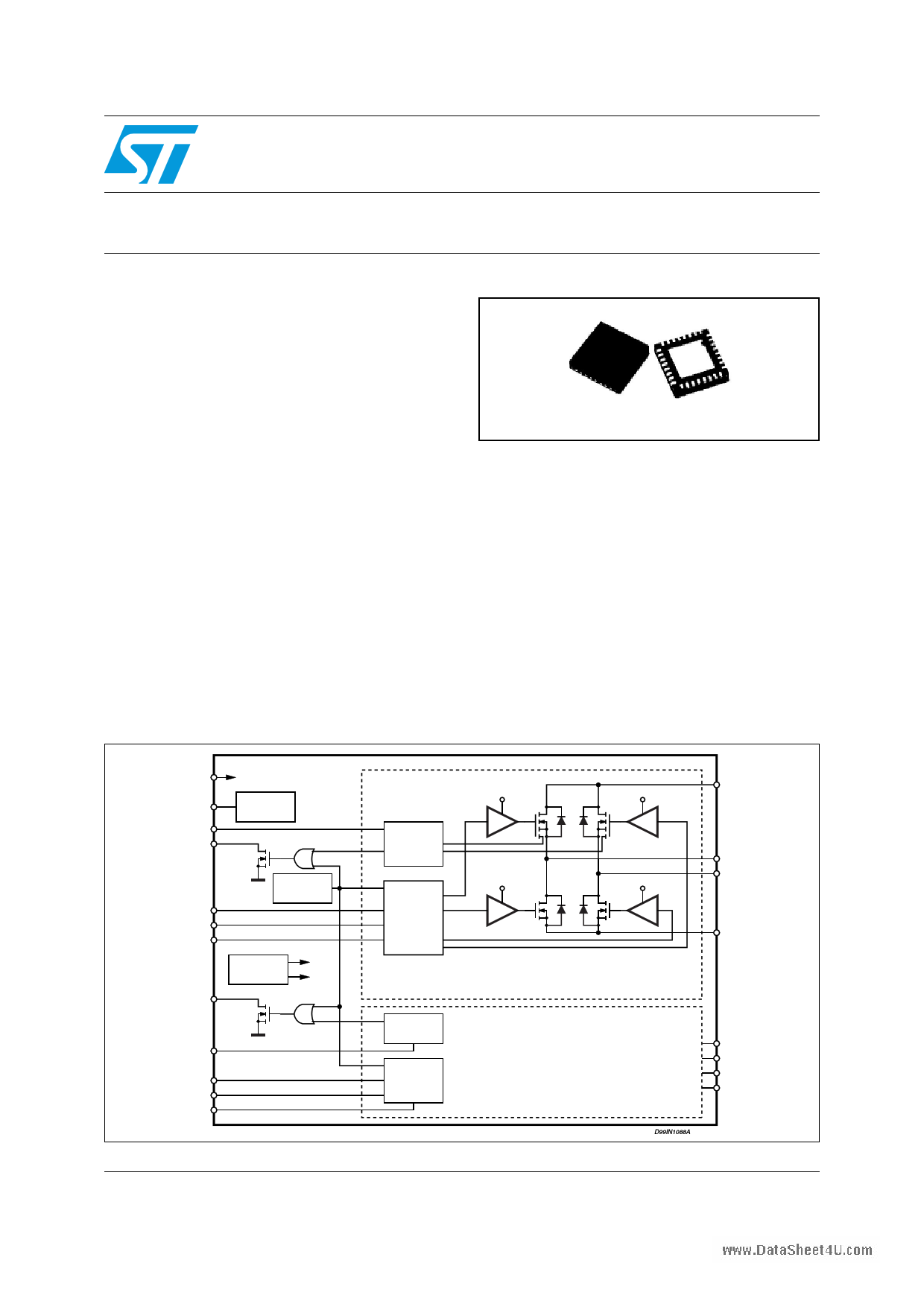
Figure 1. Block diagram
VFQFPN32 5 mm x 5 mm
Description
The L6226Q is a DMOS dual full bridge designed
for motor control applications, realized in
BCDmultipower technology, which combines
isolated DMOS power transistors with CMOS and
bipolar circuits on the same chip. Available in
QFN32 5x5 package, the L6226Q features
thermal shutdown and a non-dissipative
overcurrent detection on the high side power
MOSFETs plus a diagnostic output that can be
easily used to implement the overcurrent
protection.
VBOOT
VCP
PROGCLA
OCDA
VBOOT
CHARGE
PUMP
OCDA
ENA
IN1A
IN2A
OCDB
PROGCLB
ENB
IN1B
IN2B
THERMAL
PROTECTION
VOLTAGE
REGULATOR
10V
5V
OCDB
June 2008
OVER
CURRENT
DETECTION
GATE
LOGIC
VBOOT
10V
OVER
CURRENT
DETECTION
GATE
LOGIC
Rev 2
VBOOT
VSA
OUT1A
OUT2A
10V
SENSEA
BRIDGE A
BRIDGE B
D99IN1088A
VSB
OUT1B
OUT2B
SENSEB
1/28
www.st.com
28
1 page 
L6226Q
2 Pin connection
Figure 2. Pin connection (top view)
www.DataSheet4U.com
Pin connection
Note: 1 The pins 2 to 8 are connected to die PAD.
2 The die PAD must be connected to GND pin.
5/28
5 Page 
L6226Q
4.3 Truth table
www.DataSheet4U.com
Table 7.
Truth table
Inputs
EN IN1
L X (1)
HL
HH
HL
HH
1. X = Don't care
2. High Z = High impedance output
Circuit description
Outputs
IN2
OUT1
OUT2
X
High Z (2)
High Z
L
GND
GND
L Vs GND
H GND Vs
H Vs Vs
4.4 Non-dissipative overcurrent detection and protection
An overcurrent detection circuit (OCD) is integrated. This circuit can be used to provides
protection against a short circuit to ground or between two phases of the bridge as well as a
roughly regulation of the load current. With this internal over current detection, the external
current sense resistor normally used and its associated power dissipation are eliminated.
Figure 7 shows a simplified schematic of the overcurrent detection circuit for the bridge A.
bridge B is provided of an analogous circuit.
To implement the over current detection, a sensing element that delivers a small but precise
fraction of the output current is implemented with each high side power MOS. Since this
current is a small fraction of the output current there is very little additional power
dissipation. This current is compared with an internal reference current IREF. When the
output current reaches the detection threshold Isover the OCD comparator signals a fault
condition. When a fault condition is detected, an internal open drain MOS with a pull down
capability of 4 mA connected to OCD pin is turned on. Figure 8 shows the OCD operation.
This signal can be used to regulate the output current simply by connecting the OCD pin to
EN pin and adding an external R-C as shown in Figure 7. The off time before recovering
normal operation can be easily programmed by means of the accurate thresholds of the
logic inputs.
IREF and, therefore, the output current detection threshold are selectable by RCL value,
following the equations:
● Isover = 2.8 A ± 30 % at -25 °C < TJ < 125 °C if RCL = 0 Ω
(PROGCL connected to GND)
●
Isover =
1----1---0----5---0--
RCL
±10 % at -25 °C < TJ < 125 °C if 5 kΩ < RCL < 40 kΩ
Figure 9 shows the output current protection threshold versus RCL value in the range 5 kΩ
to 40 kΩ.
The disable time tDISABLE before recovering normal operation can be easily programmed by
means of the accurate thresholds of the logic inputs. It is affected whether by CEN and REN
11/28
11 Page | ||
| Páginas | Total 28 Páginas | |
| PDF Descargar | [ Datasheet L6226Q.PDF ] | |
Hoja de datos destacado
| Número de pieza | Descripción | Fabricantes |
| L6226 | DMOS DUAL FULL BRIDGE DRIVER | STMicroelectronics |
| L6226D | DMOS DUAL FULL BRIDGE DRIVER | STMicroelectronics |
| L6226N | DMOS DUAL FULL BRIDGE DRIVER | STMicroelectronics |
| L6226PD | DMOS DUAL FULL BRIDGE DRIVER | STMicroelectronics |
| Número de pieza | Descripción | Fabricantes |
| SLA6805M | High Voltage 3 phase Motor Driver IC. |
Sanken |
| SDC1742 | 12- and 14-Bit Hybrid Synchro / Resolver-to-Digital Converters. |
Analog Devices |
|
DataSheet.es es una pagina web que funciona como un repositorio de manuales o hoja de datos de muchos de los productos más populares, |
| DataSheet.es | 2020 | Privacy Policy | Contacto | Buscar |