|
|
|
PDF NJW1191 Data sheet ( Hoja de datos )
| Número de pieza | NJW1191 | |
| Descripción | 4-channel Electronic Volume | |
| Fabricantes | New Japan Radio | |
| Logotipo | ||
Hay una vista previa y un enlace de descarga de NJW1191 (archivo pdf) en la parte inferior de esta página. Total 20 Páginas | ||
|
No Preview Available !
NJW1191
4-channel Electronic Volume with Input Selector
!GENERAL DESCRIPTION
NJW1191 is 4-channel Electronic Volume with input
selector. It includes main volume, balance and fader trim, 4
inputs selector, loudness and tone control.
NJW1191 performs low noise and low distortion
characteristics with resistance ladder type electrical volume.
All of internal status and variables are controlled by I2C BUS
interface.
www.DataSheet4U.com
!PACKAGE OUTLINE
NJW1191V
!FEATURES
●Operating Voltage
●I2C BUS Interface
●Low Output Noise
●Low Distortion
●4ch Input Selector
●Loudness
●Tone Control
●Main Volume
●Balance & Fader
●Bi-CMOS Technology
●Package Outline
7.5 to 13V
-103dBVtyp
0.01%typ
Bass / Treble
SSOP32
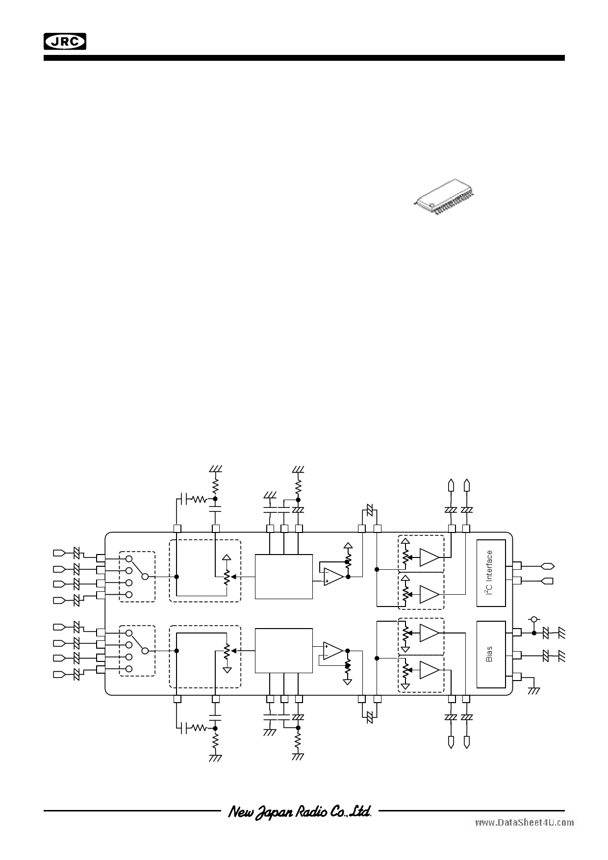
!BLOCK DIAGRAM
Tone
Tone
0dB,+6dB
,+12dB,+18dB
0dB,+6dB
,+12dB,+18dB
–1–
1 page 
NJW1191
!APPLICATION CIRCUIT
www.DataSheet4U.com
C25 100µF
+
C1 10µF
1
+
C2 1µF
+
C3 1µF
2
3
+4
C4 1µF
+
C5 1µF
+
5
6
C6 470pF
7
C7 100nF
R1 39kΩ
8
R2 4.7kΩ
C8 4.7nF
9
C9 100nF
10
R3 2.2kΩ
C10 4.7µF
+ 11
GND
VREF
MASTER
VOLUME
& LOUDNESS
TONE
CONTROL
BIAS
V+
MASTER
VOLUME
& LOUDNESS
TONE
CONTROL
32
+9V
31
C2+4 1µF
30
C23 1µF
+
29
C22
+
1µF
28
C2+1 1µF
27
C21 470pF
26
R8 39kΩ C20 100nF
25
R7 4.7kΩ
C19 4.7nF
24
C18 100nF
23
C17 4.7µF
22 +
R6 2.2kΩ
+
C11 1µF
12
13
C12 10µF
+
C13 10µF
+
R4 100Ω
14
15
16
FRONT
VOLUME
REAR
VOLUME
SCL
I2C BUS
INTERFACE
FRONT
VOLUME
REAR
VOLUME
SDA
21 +
C16 1µF
20
C+15 10µF
19
C+14 10µF
18
R5 100Ω
17
!APPLICATION NOTES
Pin No.
Function
Note
2
VREF
C1 can be adjusted rise and fall time of reference voltage at power on and off. Take care that the reduced C1makes
sensitive to ripple of power supply.
3 - 6, 27 -30 Inputs
The Input impedance is designed about 48k ohms. The ground line should be inserted between each input lines to
avoid cross talk.
7,8,25,26
Loudness filter
Taps
Loudness frequency can be adjusted with external parts(See page 6) . Especialy, 8 and 25 pins should be kept from
large signal lines such as digital signal lines or the other sound signal lines to avoid digitaly noise or cross talk in
Loudness mode.
9,10,11,22,23, Tone filter
24 terminals
Tone Bass and Treble cut off frequency can be adjusted with external parts(See page6). These pins should be kept
from large signal lines such as digital signal lines or the other sound signal lines to avoid the digitaly noise or cross
talk.
12,21
Tone outputs Output impedance is designed about 50 ohms.
13,20
Balance Fedar
volume inputs
Input impedance is designed about 24k ohms.
14,15,18,19
Balance Fedar
volume
Output impedance is designed about 50 ohms.
outputs
16,17
I2C control
signal ports
These terminals should be inserted resistance about 100 ohms between terminal and signal source to reduce the
digitaly noise. These lines should be kept from analog signal lines and or near by the chip to avoid digitaly noise.
Inserted ground line between analog line and digital line should be recommended.
–5–
5 Page 
NJW1191
!INSTRUCTION CODE
a) MAIN VOLUME (VOL1,Amp Gain) SETTING
Select
BIT
Address
D7
D6 D5 D4
D3
D2
D1
D0
00H
Amp Gain
VOL1
•Amp Gain : 0dB, +6dB, +12dB, +18dB
•VOL1 : Volume 1 Attenuator setting 0 to –30dB (1dB/Step),-30 to –68dB (2dB/Step),Mute
b) BALANCE, FADER VOLUME (VOL2FL,FR,RL,RR ) SETTING
www.DataSheet4U.com
Select
BIT
Address
D7
D6
D5
D4
D3
01H
VOL2FL
02H
VOL2RL
D2 D1
VOL2FR
VOL2RR
D0
•VOL2FL,FR,RL,RR : 0,-2,-4,-6,-8,-10,-12,-16,-18,-20,-24,-32,-34,-36,-38,-42 dB
c) TONE SETTING
Select
Address
D7
03H BCB
BIT
D6 D5 D4 D3
TONE BASS
BCT
D2 D1 D0
TONE TREBLE
•BCB : Boost cut select for Bass control
“0” : Cut
“1” : Boost
•TONE BASS : BASS Level Setting
Cut Level : -14 to 0dB(2dB/Step)
Boost Level : 0 to +14dB(2dB/Step)
•BCT : Boost cut select for Treble control
“0” : Cut
“1” : Boost
•TONE TREBLE : TREBLE Level Setting
Cut Level : -14 to 0dB(2dB/Step)
Boost Level : 0 to +14dB(2dB/Step)
d) INPUT SELECTOR SETTING
Select
Address
D7
D6
04H
FLMute FRMute
D5
RLMute
BIT
D4 D3
D2
RRMute
Input Selector
D1
Loudness
D0
Test
•FLMute, FRMute, RLMute, RRMute : VOL2FL,FR,RL,RR Mute
•Input Selector: INPUT1 to 4
•Loudness : Loudness ON/OFF
•Test : For device check use only. Set D0 = 0 in usual.
– 11 –
11 Page | ||
| Páginas | Total 20 Páginas | |
| PDF Descargar | [ Datasheet NJW1191.PDF ] | |
Hoja de datos destacado
| Número de pieza | Descripción | Fabricantes |
| NJW1190 | Audio Processor / QFP48-P1 / SSOP44 | JRC |
| NJW1191 | 4-channel Electronic Volume | New Japan Radio |
| NJW1192 | Electronic Volume / SSOP32 | JRC |
| NJW1194 | 2-CHANNEL ELECTRONIC VOLUME | New Japan Radio |
| Número de pieza | Descripción | Fabricantes |
| SLA6805M | High Voltage 3 phase Motor Driver IC. |
Sanken |
| SDC1742 | 12- and 14-Bit Hybrid Synchro / Resolver-to-Digital Converters. |
Analog Devices |
|
DataSheet.es es una pagina web que funciona como un repositorio de manuales o hoja de datos de muchos de los productos más populares, |
| DataSheet.es | 2020 | Privacy Policy | Contacto | Buscar |