|
|
|
PDF LH5P8129 Data sheet ( Hoja de datos )
| Número de pieza | LH5P8129 | |
| Descripción | CMOS 1M (128K x 8) CS-Control Pseudo-Static RAM | |
| Fabricantes | Sharp Electrionic Components | |
| Logotipo | ||
Hay una vista previa y un enlace de descarga de LH5P8129 (archivo pdf) en la parte inferior de esta página. Total 14 Páginas | ||
|
No Preview Available !
LH5P8129
CMOS 1M (128K × 8)
CS-Control Pseudo-Static RAM
FEATURES
• 131,072 × 8 bit organization
• Access times (MAX.): 60/80/100 ns
• Cycle times (MIN.): 100/130/160 ns
• Single +5 V power supply
• Pin compatible with 1M standard SRAM
• Power consumption:
Operating: 572/385/275 mW (MAX.)
Standby (TTL level): 5.5 mW (MAX.)
Standby (CMOS level): 1.1 mW (MAX.)
• TTL compatible I/O
• Available for auto-refresh and self-refresh
modes
• 512 refresh cycles/8 ms
• Packages:
32-pin, 600-mil DIP
32-pin, 525-mil SOP
32-pin, 8 × 20 mm2 TSOP (Type I)
DESCRIPTION
The LH5P8129 is a 1M bit Pseudo-Static RAM
organized as 131,072 × 8 bits. It is fabricated using
silicon-gate CMOS process technology.
A PSRAM uses on-chip refresh circuitry with a DRAM
memory cell for pseudo static operation which elimi-
nates external clock inputs, while considering the pinout
compatibility with industry standard SRAMs. The
advantage is the cost savings realized with the lower
cost PSRAM.
The LH5P8129 PSRAM has a built-in oscillator, which
makes it easy to refresh memories without external
clocks.
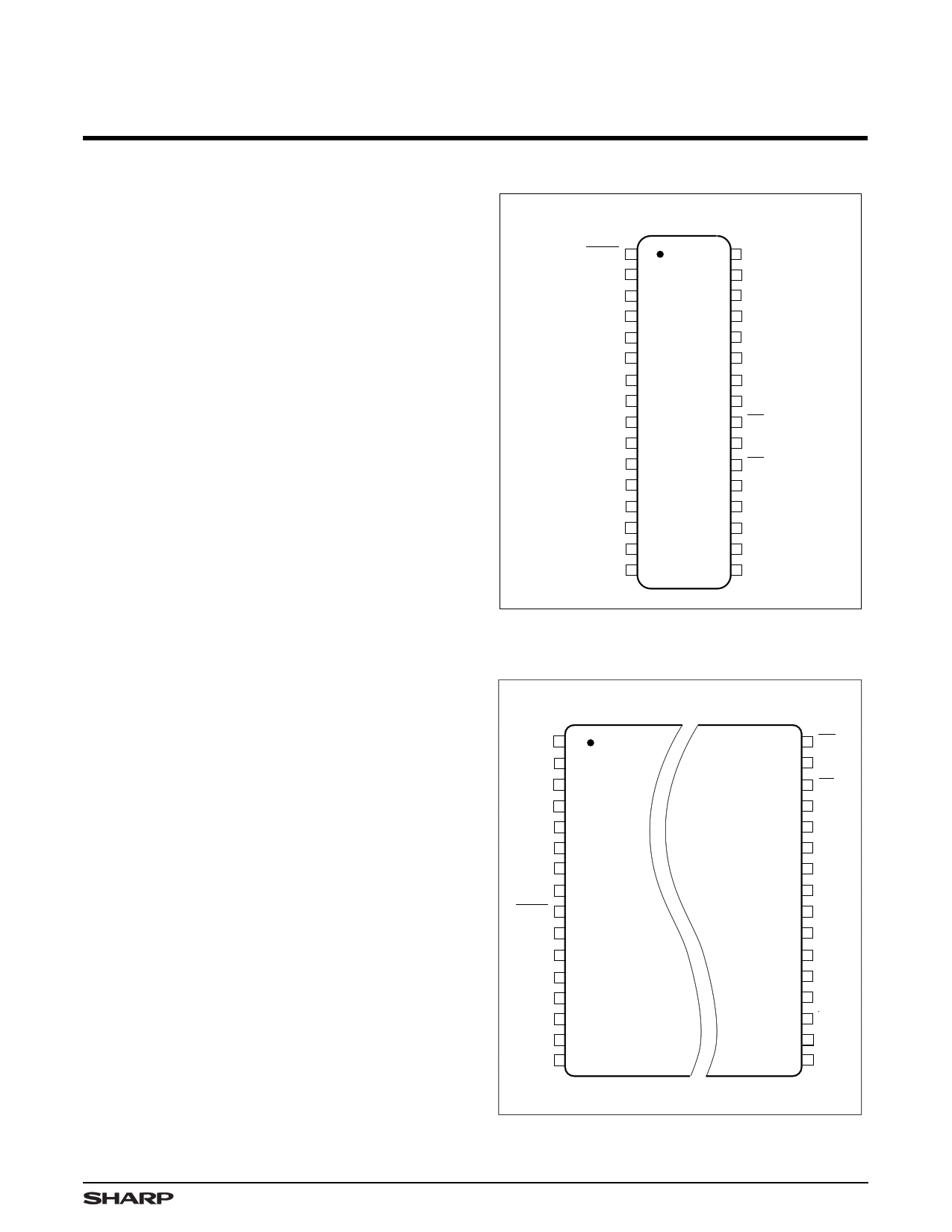
PIN CONNECTIONS
32-PIN DIP
32-PIN SOP
TOP VIEW
RFSH
A16
A14
A12
A7
A6
A5
A4
A3
A2
A1
A0
I/O0
I/O1
I/O2
GND
1
2
3
4
5
6
7
8
9
10
11
12
13
14
15
16
32 VCC
31 A15
30 CS
29 R/W
28 A13
27 A8
26 A9
25 A11
24 OE
23 A10
22 CE
21 I/O7
20 I/O6
19 I/O5
18 I/O4
17 I/O3
5P8129-1
Figure 1. Pin Connections for DIP and
SOP Packages
32-PIN TSOP (Type I)
TOP VIEW
A11
A9
A8
A13
R/W
CS
A15
VCC
RFSH
A16
A14
A12
A7
A6
A5
A4
1
2
3
4
5
6
7
8
9
10
11
12
13
14
15
16
32 OE
31 A10
30 CE
29 I/O7
28 I/O6
27 I/O5
26 I/O4
25 I/O3
24 GND
23 I/O2
22 I/O1
21 I/O0
20 A0
19 A1
18 A2
17 A3
NOTE: Reverse bend available on request.
5P8129-2
Figure 2. Pin Connections for TSOP Package
1
1 page 
CMOS 1M (128K × 8) Pseudo-Static RAM
LH5P8129
AC ELECTRICAL CHARACTERISTICS 1,2,3 (TA = 0 to +70°C, VCC = 5.0 V ±10%)
PARAMETER
SYMBOL
LH5P8129-60
MIN.
MAX.
LH5P8129-80
MIN. MAX.
LH5P8129-10
MIN. MAX.
UNIT NOTE
Random read, write cycle time
Read modify write cycle time
CE pulse width
CE precharge time
CS setup time
CS hold time
Address setup time
Address hold time
Read command setup time
Read command hold time
CE access time
OE access time
CE to output in Low-Z
OE to output in Low-Z
Output enable from end of write
Chip disable to output in High-Z
Output disable to output in High-Z
Write enable to output in High-Z
OE setup time
OE hold time
Write command pulse width
Write command setup time
Write command hold time
Data setup time from write
Data setup time from CE
Data hold time from write
Data hold time from CE
Transition time (rise and fall)
Refresh time interval
Refresh command hold time
Auto refresh cycle time
Refresh delay time from CE
Refresh pulse width
(Auto refresh)
Refresh precharge time
(Auto refresh)
Refresh pulse width (Self refresh)
CE delay time from refresh
precharge (Self refresh)
tRC
tRMW
tCE
tP
tCSS
tCSH
tAS
tAH
tRCS
tRCH
tCEA
tOEA
tCLZ
tOLZ
tWLZ
tCHZ
tOHZ
tWHZ
tOES
tOEH
tWP
tWCS
tWCH
tDSW
tDSC
tDHW
tDHC
tT
tREF
tRHC
tFC
tRFD
tFAP
tFP
tFAS
tFRS
100 130 160 ns
165 195 235 ns
60 10,000 80 10,000 100 10,000 ns
40 40 50 ns
0 0 0 ns
15 20 25 ns
0 0 0 ns
15 20 25 ns
0 0 0 ns
0 0 0 ns
60 80 100 ns
25 30 35 ns
20 20 20 ns
0 0 0 ns
0 0 0 ns
20 25 30 ns
20 25 30 ns
20 25 30 ns
0 0 0 ns
10 10 10 ns
30 30 30 ns
30 30 30 ns
40 50 60 ns
25 30 35 ns
25 30 35 ns
0 0 0 ns
0 0 0 ns
3 35 3 35 3 35 ns
8 8 8 ms
15 15 15 ns
100 130 160 ns
30 40 50 ns
30 8,000 30 8,000 30 8,000 ns
30
8,000
140
30
8,000
160
30
8,000
190
ns
ns
ns
4
4
5
5
6
6
6
6
NOTES:
1. In order to initialize the circuit, an initial pause of 100 µs with
CE = VIH, RFSH = VIH after power-up, followed by at least 8
dummy cycles.
2. AC characteristics are measured at tT = 5 ns.
3. AC characteristics are measured at the following condition (see
figure at right).
4. Measured with a load equivalent to 2TTL + 100 pF.
5. Address is latched at the negative edge of CE.
6. Data is latched at the positive edge of R/W or at the positive
edge of CE.
INPUT
OUTPUT
2.4 V
0.8 V
2.2 V
0.8 V
2.6 V
0.6 V
5P8129-4
Figure 4. AC Characteristics
5
5 Page 
CMOS 1M (128K × 8) Pseudo-Static RAM
CE
VIH
VIL
CS
VIH
VIL
A0 - A8
VIH
VIL
OE
VIH
VIL
R/W
VIH
VIL
I/O0 - I/O7
VOH
VOL
RFSH
VIH
VIL
NOTE: A9 - A16 = Don't Care
tRC
tP tCE
tCSS
tCSH
tAS tAH
ADDRESS INPUT
tOES
tRCS
tFP
tFRS tRHC
HIGH-Z
Figure 10. CE Only Refresh
LH5P8129
tOEH
tRCH
tRFD
5P8129-10
CE
VIH
VIL
tRFD
tFP
tFAP
tFC
tFP
tFC
tFAP
RFSH VIH
VIL
I/O0 - I/O7
VOH
VOL
NOTE: CS, OE, R/W, A0 -A16 = Don't Care
HIGH-Z
Figure 11. Auto Refresh Cycle
tRHC
tFP
5P8129-11
11
11 Page | ||
| Páginas | Total 14 Páginas | |
| PDF Descargar | [ Datasheet LH5P8129.PDF ] | |
Hoja de datos destacado
| Número de pieza | Descripción | Fabricantes |
| LH5P8128 | CMOS 1M (128K x 8) Pseudo-Static RAM | Sharp Electrionic Components |
| LH5P8129 | CMOS 1M (128K x 8) CS-Control Pseudo-Static RAM | Sharp Electrionic Components |
| Número de pieza | Descripción | Fabricantes |
| SLA6805M | High Voltage 3 phase Motor Driver IC. |
Sanken |
| SDC1742 | 12- and 14-Bit Hybrid Synchro / Resolver-to-Digital Converters. |
Analog Devices |
|
DataSheet.es es una pagina web que funciona como un repositorio de manuales o hoja de datos de muchos de los productos más populares, |
| DataSheet.es | 2020 | Privacy Policy | Contacto | Buscar |