|
|
|
PDF IR22771S Data sheet ( Hoja de datos )
| Número de pieza | IR22771S | |
| Descripción | Phase Current Sensor IC | |
| Fabricantes | International Rectifier | |
| Logotipo | ||
Hay una vista previa y un enlace de descarga de IR22771S (archivo pdf) en la parte inferior de esta página. Total 16 Páginas | ||
|
No Preview Available !
Data Sheet No. PD60234 revB
IR22771S/IR21771S(PbF)
Phase Current Sensor IC for AC motor control
Features
• Floating channel up to 600V for IR21771 and 1200V for
IR22771
• Synchronous sampling measurement system
•www.DataSheet4U.comHigh PWM noise (ripple) rejection capability
• Digital PWM output
• Fast Over Current detection
• Suitable for bootstrap power supplies
• Low sensing latency (<7.5 µsec @20kHz)
Product Summary
VOFFSET (max)
IR22771
IR21771
Vin range
Bootstrap supply range
Floating channel quiescent
current (max)
Sensing latency (max)
Throughput
Over Current threshold (max)
1200 V
600V
±250mV
8-20 V
2.2 mA
7.5 µsec
(@20kHz)
40ksample/sec
(@20kHz)
±470 mV
Description
IR21771/IR22771 is a high voltage, high speed, single phase
current sensor interface for AC motor drive applications. The
current is sensed by an external shunt resistor. The IC converts the
analog voltage into a time interval through a precise circuit that also
performs a very good ripple rejection showing small group delay.
The time interval is level shifted and given to the output. The max
throughput is 40 ksample/sec suitable for up to 20 kHz
asymmetrical PWM modulation and max delay is <7.5µsec
(@20kHz). Also a fast over current signal is provided for IGBT
protection.
Package
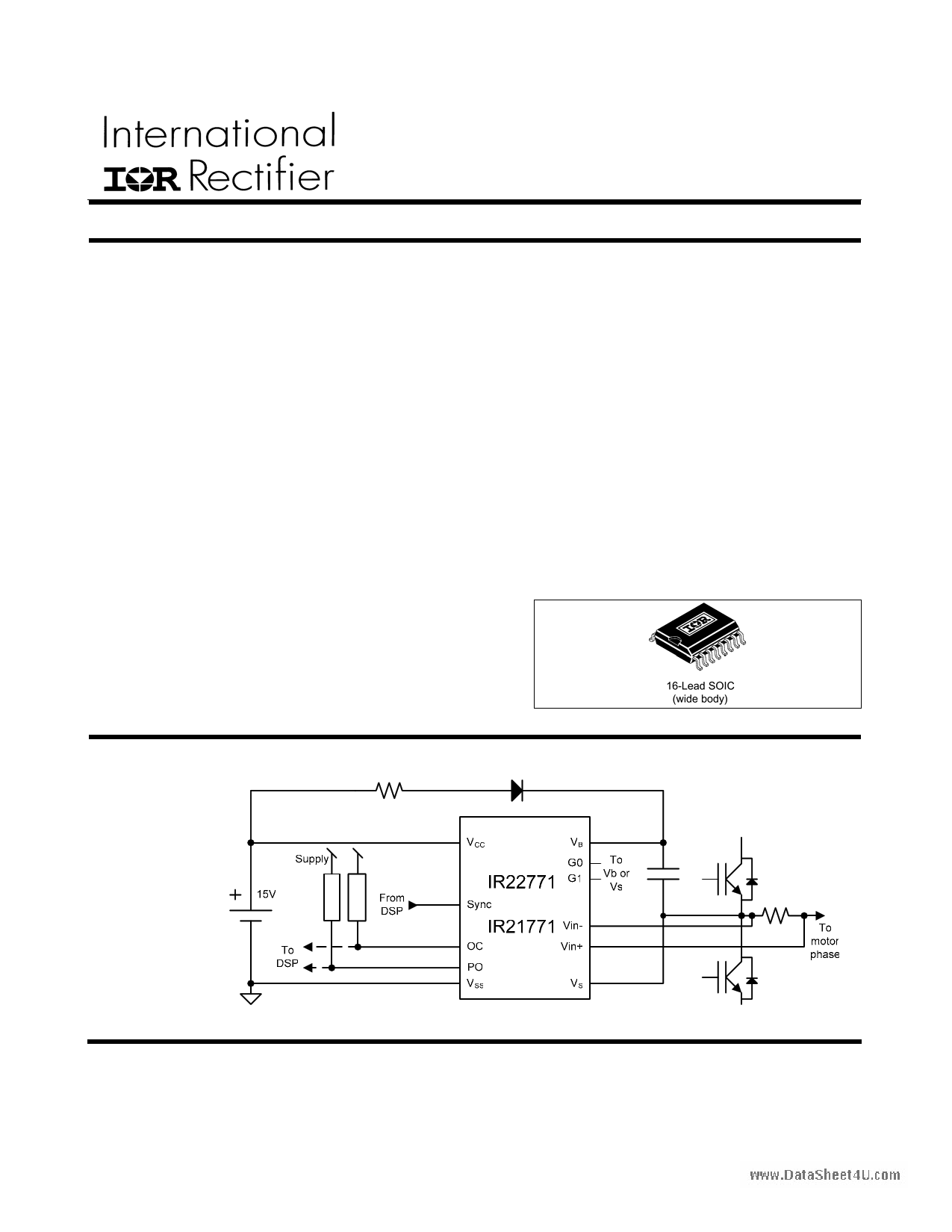
Typical Connection
(Please refer to
Lead Assignments
for correct pin
configuration. This
diagram shows
electrical
connections only)
1
www.irf.com
1 page 
AC Electrical Characteristics
VBIAS (VCC, VBS) = 15V unless otherwise specified. Temp=27°C.
IR22771S/IR21771S(PbF)
Symbol
Definition
fsync PWM frequency
fout Throughput
BW Bandwidth (@ -3 dB)
GD
www.DataSheet4U.com
Dmin
Group Delay (input filter)
Minimum Duty Cycle (Note 1)
Min Typ
4
2 ⋅ fsync
fsync
1
4 ⋅ fsync
10
Max Units
20 kHz
ksample/sec
kHz
µs
%
Test
Conditions
Vin=+Vinmax
Dmax
Maximum Duty Cycle (Note 1)
30
% Vin=-Vinmin
tdOCon
De-bounce time of OC
2.7 3.5
4.7
µs See Figure 4
TOCoff
Time to reset OC forcing PO
MD Measure Delay
SR
Step response (max time to reach
steady state)
Note 1: negative logic, see fig. 4 on page 7
Note 2: Cload < 5 nF avoids overshoot
0.51
fsync
0.5
0.30
2 ⋅ fsync
1.3
fsync
µs
µs
µs
See Figure 4
See Figure 5
Figure 4: OC timing diagram
5 www.irf.com
5 Page 
1.4 DC transfer functions
The working principle of the device can be easily
explained by Figure 10, in which the main signals
are represented.
Triangular
reference
SYNC
Vin
www.DataSheet4U.cPoOm
Figure 10: Main current sensor signals and
outputs
PWM out (PO pin) gives a duty cycle which is
inversely proportional to the input signal.
Eq. 2 gives the resulting Dn of the PWM output (PO
pin):
Eq.
2 Dn
=
20% − 40 %
V
⋅ Vin
where Vin = Vinp-Vinm
PO duty cycle
30%
25%
20%
15%
10%
Vin
Figure 11: PO Duty Cycle (Dn)
IR22771S/IR21771S(PbF)
1.5 Filter AC characteristic
IR21771/22771 signal path can be considered as
composed by three stages in series (see Figure 13).
The first two stages perform the filtering action.
Stage 1 (input filter) implements the filtering action
originating the transfer function shown in Figure 14.
The input filter is a self-adaptive reset integrator
which performs an accurate ripple cancellation. This
stage extracts automatically the PWM frequency
from Sync signal and puts transmission zeros at
even harmonics, rejecting the unwanted PWM
noise.
The following timing diagram shows the principle by
which even harmonics are rejected (Figure 12).
Figure 12: Even harmonic cancellation principle
As can be seen from Figure 14, the odd harmonics
are rejected as a first order low pass filter with a
single pole placed in fPWM.
The input filter group delay in the pass-band is very
low (see GD on AC electrical characteristics) due to
the beneficial action of the zeroes.
11 www.irf.com
11 Page | ||
| Páginas | Total 16 Páginas | |
| PDF Descargar | [ Datasheet IR22771S.PDF ] | |
Hoja de datos destacado
| Número de pieza | Descripción | Fabricantes |
| IR22771S | Phase Current Sensor IC | International Rectifier |
| Número de pieza | Descripción | Fabricantes |
| SLA6805M | High Voltage 3 phase Motor Driver IC. |
Sanken |
| SDC1742 | 12- and 14-Bit Hybrid Synchro / Resolver-to-Digital Converters. |
Analog Devices |
|
DataSheet.es es una pagina web que funciona como un repositorio de manuales o hoja de datos de muchos de los productos más populares, |
| DataSheet.es | 2020 | Privacy Policy | Contacto | Buscar |