|
|
|
PDF N82C55AN Data sheet ( Hoja de datos )
| Número de pieza | N82C55AN | |
| Descripción | IN82C55AN | |
| Fabricantes | Integral | |
| Logotipo | ||
Hay una vista previa y un enlace de descarga de N82C55AN (archivo pdf) en la parte inferior de esta página. Total 21 Páginas | ||
|
No Preview Available !
IN82C55AN
CHMOS PROGRAMMABLE PERIPHERAL INTERFACE
The Integral IN82C55AN is a high-performance, CHMOS version of the industry standard
IN82C55AN general purpose programmable I/O device which is designed for use with all
Intel and most other microprocessors. It provides 24 I/O pins which may be individually
programmed in 2 groups of 12 and used in 3 major modes of operation.
In MODE 0, each group of 12 I/O pins may be programmed in sets of 4 and 8 to be inputs
or outputs. In MODE 1, each group may be programmed to have 8 lines of input or output.
3 of the remaining 4 pins are used for handshaking and interrupt control signals. MODE 2
is a strobed bi-directional bus configuration.
FEATURES
www.DataSheet4U.com
• Compatible with all Intel and Most Other Microprocessors
• High Speed, «Zero Wait State» Operation with 8MHz 8086/88 and 80186/188
• 24 Programmable I/O Pins
• Low Power CHMOS
• Completely TTL Compatible
• Control Word Read-Back Capability
• Direct Bit Set/Reset Capability
• 2.5mA DC Drive Capability on all I/O Port Outputs
• Available in 40-Pin DIP
• Available in EXPRESS
Standard Temperature Range
Extended Temperature Range
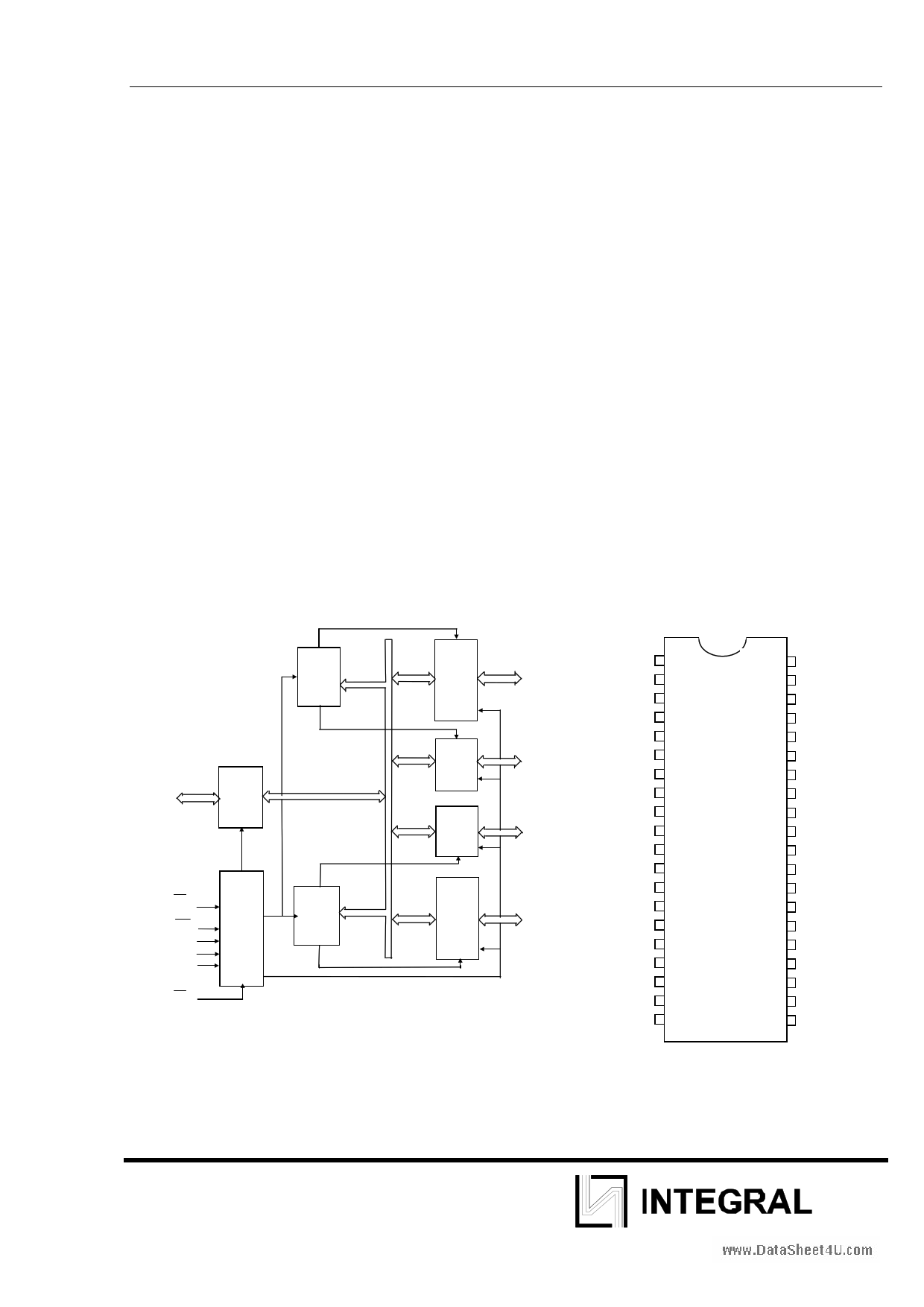
GROUP
A
CONTROL
D7-D0
DATA
BUS
BUFFER
8 BIT
INTERNAL
DATA BUS
RD
WR
A1
A0
Reset
CS
READ/
WRITE
CONTROL
LOGIC
GROUP
B
CONTROL
Figure 1
GROUP
A
PORT
A
(8)
GROUP
A
PORT C
UPPER
(4)
GROUP
B
PORT C
LOWER
(4)
GROUP
B
PORT
B
(8)
PA7-PA0
PC7-PC4
PC3-PC0
PB7-PB0
PA3
PA2
PA1
PA0
RD
CS
VSS
A1
A0
PC7
PC6
PC5
PC4
PC0
PC1
PC2
PC3
PB0
PB1
PB2
1. 40
2. 39
3. 38
4. 37
5. 36
6. 35
7. 34
8. 33
9. 32
10 31
11 30
12 29
13 28
14 27
15 26
16 25
17 24
18 23
19 22
20 21
Figure 2
PA4
PA5
PA6
PA7
WR
Reset
D0
D1
D2
D3
D4
D5
D6
D7
VCC
PB7
PB6
PB5
PB4
PB3
1
1 page 
IN82C55AN
IN82C55AN OPERATIONAL DESCRIPTION
Mode Selection
There are three basic modes of operation that can be selected by the system software:
Mode 0 - Basic input/output
Mode 1 - Strobed Input/output
Mode 2 - Bi-directional Bus
When the reset input goes “high” all ports will be set to the input mode with all 24 port lines held at a logic
“one” level by the internal bus hold devices (see Figure 4 Note). After the reset is removed the IN82C55AN
can remain in the input mode with no additional initialization required. This eliminates the need for pullup or
pulldown devices in “all CMOS” designs. During the execution of the system program, any of the other
modes may be selected by using a single output instruction. This allows a single IN82C55AN to service a
www.DataSheet4U.comvariety of peripheral devices with a simple software maintenance routine.
The modes for Port A and Port B can be separately defined, while Port C is divided into two portions as
required by the Port A and Port B definitions. All of the output registers, including the status flip-flops, will be
reset whenever the mode is changed. Modes may be combined so that their functional definition can be
“tailored” to almost any I/O structure. For instance; Group B can be programmed in Mode 0 to monitor simple
switch closings or display computational results, Group A could be programmed in Mode 1 to monitor a
keyboard or tape reader on an interrupt-driven basis.
ADRESS BUS
CONTROL BUS
DATA BUS
8
MODE 0
RD, WR
B
D7-D0
C
A0, A1
A
8
PB7-PB0
4
PC3-PC0
4
PC7-PC4
8
PA7-PA0
MODE 1
B
CA
8
PB7-PB0
CONTROL
OR I/O
CONTROL
OR I/O
8
PA7-PA0
MODE 2
B
8
PB7-PB0
C
I/O CONTROL
A
8
PA7-PA0
Figure 5. Basic Mode Definitions and Bus Interface
5
5 Page 
Operating Modes
IN82C55AN
MODE 1 (Strobed Input/Output). This functional configuration provides a means for transferring I/O data to
or from a specified port in conjunction with strobes or “handshaking” signals. In mode 1, Port A and Port B
use the lines on Port C to generate or accept these “handshaking” signals.
Mode 1 Basic functional Definitions:
• Two Groups (Group A and Group B).
• Each group contains one 8-bit data port and one 4-bit control/data port.
• The 8-bit data port can be either input or output
• Both inputs and outputs are latched.
• The 4-bit port is used for control and status of the
• 8-bit data port.
Input Control Signal Definition
www.DataSheet4U.comSTB (Strobe Input). A “low” on this input loads data into the input latch.
IBF (Input Buffer Full F/F)
A “high” on this output indicates that the data has been loaded into the input latch; in essence, an
acknowledgement. IBF is set by STB input being low and is reset by the rising edge of the RD input.
INTR (Interrupt Request)
A “high” on this output can be used to interrupt the CPU when an input device is requesting service. INTR is
set by the STB is a “one”, IBF is a “one” and INTE is a “one”. It is reset by the falling edge of RD . This
procedure allows an input device to request service from the CPU by simply strobing its data into the port.
INTE A
Controlled by bit set/reset of PC4.
INTE B
Controlled by bit set/reset of PC2
MODE 1 (PORT A)
CONTROL WORD
D7 D6 D5 D4 D3 D2 D1 D0
1 0 1 1 1/0 X X X
PC6,7
1 = INPUT
0 = OUTPUT
RD
PA7-PA0
INTE
A
PC4
PC5
8
STBA
IBFA
PC3
PC6,7
INTRA
2
MODE 1 (PORT B)
CONTROL WORD
D7 D6 D5 D4 D3 D2 D1 D0
1 XXXX 1 1 X
PB7-PB0
INTE
B
PC2
PC1
8
STBB
IBFB
RD PC0 INTRB
Figure 8. MODE 1 Input
11
11 Page | ||
| Páginas | Total 21 Páginas | |
| PDF Descargar | [ Datasheet N82C55AN.PDF ] | |
Hoja de datos destacado
| Número de pieza | Descripción | Fabricantes |
| N82C55A | CHMOS PROGRAMMABLE PERIPHERAL INTERFACE | Intel Corporation |
| N82C55AN | IN82C55AN | Integral |
| Número de pieza | Descripción | Fabricantes |
| SLA6805M | High Voltage 3 phase Motor Driver IC. |
Sanken |
| SDC1742 | 12- and 14-Bit Hybrid Synchro / Resolver-to-Digital Converters. |
Analog Devices |
|
DataSheet.es es una pagina web que funciona como un repositorio de manuales o hoja de datos de muchos de los productos más populares, |
| DataSheet.es | 2020 | Privacy Policy | Contacto | Buscar |