|
|
|
PDF DS1985 Data sheet ( Hoja de datos )
| Número de pieza | DS1985 | |
| Descripción | 16-kbit Add-Only iButton | |
| Fabricantes | Dallas Semiconductor | |
| Logotipo | ||
Hay una vista previa y un enlace de descarga de DS1985 (archivo pdf) en la parte inferior de esta página. Total 25 Páginas | ||
|
No Preview Available !
DS1985
16-kbit Add-Only iButtonTM
www.dalsemi.com
SPECIAL FEATURES
§ 16384 bits Electrically Programmable Read
Only Memory (EPROM) communicates with
the economy of one signal plus ground
§ EPROM partitioned into sixty-four 256-bit
www.DataSheet4pUa.cgoems for randomly accessing packetized
data records
§ Each memory page can be permanently
write-protected to prevent tampering
§ Device is an “add only” memory where
additional data can be programmed into
EPROM without disturbing existing data
§ Architecture allows software to patch data by
superseding an old page in favor of a newly
programmed page
§ Reduces control, address, data, power, and
programming signals to a single data pin
§ 8-bit family code specifies DS1985
communications requirements to reader
§ Reads over a wide voltage range of 2.8V to
6.0V from -40°C to +85°C; programs at
11.5V to 12.0V from -40°C to +85°C
COMMON iButton FEATURES
§ Unique, factory-lasered and tested 64-bit
registration number (8-bit family code + 48-
bit serial number + 8-bit CRC tester) assures
absolute traceability because no two parts are
alike
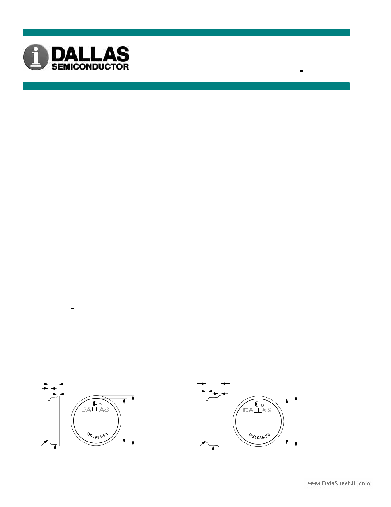
F3 MICROCAN TM
0.36
3.10
0.51
c 1993
16.25
YYWW REGISTERED RR
ED 0B
000000FBC52B
17.35
§ Multidrop controller for MicroLAN
§ Digital identification and information by
momentary contact
§ Chip-based data carrier compactly stores
information
§ Data can be accessed while affixed to object
§ Economically communicates to bus master
with a single digital signal at 16.3k bits per
second
§ Standard 16 mm diameter and 1-WireTM
protocol ensure compatibility with iButton
family
§ Button shape is self-aligning with cup-
shaped probes
§ Durable stainless steel case engraved with
registration number withstands harsh
environments
§ Easily affixed with self-stick adhesive
backing, latched by its flange, or locked with
a ring pressed onto its rim
§ Presence detector acknowledges when reader
first applies voltage
§ Meets UL#913 (4th Edit.); Intrinsically Safe
Apparatus, Approved under Entity Concept
for use in Class I, Division 1, Group A, B, C
and D Locations (application pending)
F5 MICROCAN TM
0.36
5.89
0.51
c 1993
YYWW REGISTERED RR
6D 0B
000000FBD8B3
16.25
17.35
DATA
GROUND
DATA
GROUND
All dimensions shown in millimeters.
1 of 25
090299
1 page 
DS1985
16384 BITS EPROM
The memory map in Figure 4 shows the 16384 bits EPROM section of the DS1985 which is configured
as 64 pages of 32 bytes each. The 8-bit scratchpad is an additional register that acts as a buffer when
programming the memory. Data is first written to the scratchpad and then verified by reading a 16-bit
CRC from the DS1985 that confirms proper receipt of the data and address. If the buffer contents are
correct, a programming voltage should be applied and the byte of data will be written into the selected
address in memory. This process ensures data integrity when programming the memory. The details for
reading and programming the 16384 bits EPROM portion of the DS1985 are given in the Memory
Function Commands section.
EPROM STATUS BYTES
In addition to the 16384 bits of data memory the DS1985 provides 704 bits of Status Memory accessible
www.DataShweeitt4hUs.ceopmarate commands.
The EPROM Status Bytes can be read or programmed to indicate various conditions to the software
interrogating the DS1985. The first 8 bytes of the EPROM Status Memory (addresses 000 to 007H)
contain the Write Protect Page bits which inhibit programming of the corresponding page in the 16384-bit
main memory area if the appropriate write protection bit is programmed. Once a bit has been
programmed in the Write Protect Page section of the Status Memory, the entire 32-byte page that
corresponds to that bit can no longer be altered but may still be read.
The next 8 bytes of the EPROM Status Memory (addresses 020 to 027H) contain the Write Protect bits
which inhibit altering the Page Address Redirection Byte corresponding to each page in the 16384-bit
main memory area.
The following 8 bytes within the EPROM Status Memory (addresses 040 to 047H) are reserved for use
by the iButton operating software TMEX. Their purpose is to indicate which memory pages are already in
use. Originally, all of these bits are unprogrammed, indicating that the device does not store any data. As
soon as data is written to any page of the device under control of TMEX, the bit inside this bitmap
corresponding to that page will be programmed to 0, marking this page as used. These bits are application
flags only and have no impact on the internal logic of the DS1985.
The next 64 bytes of the EPROM Status Memory (addresses 100H to 13FH) contain the Page Address
Redirection Bytes which indicate if one or more of the pages of data in the 16384 bits EPROM section
have been invalidated by software and redirected to the page address contained in the appropriate
redirection byte. The hardware of the DS1985 makes no decisions based on the contents of the Page
Address Redirection Bytes. These additional bytes of Status EPROM allow for the redirection of an entire
page to another page address, indicating that the data in the original page is no longer considered relevant
or valid. With EPROM technology, bits within a page can be changed from a logical 1 to a logical 0 by
programming, but cannot be changed back. Therefore, it is not possible to simply rewrite a page if the
data requires changing or updating, but with space permitting, an entire page of data can be redirected to
another page within the DS1985 by writing the one’s complement of the new page address into the Page
Address Redirection Byte that corresponds to the original (replaced) page.
This architecture allows the user’s software to make a “data patch” to the EPROM by indicating that a
particular page or pages should be replaced with those indicated in the Page Address Redirection Bytes.
To leave an authentic audit trail of data patches, it is recommended to also program the write protect bit
of the Page Address Redirection Byte, after the page redirection is programmed. Without this protection,
it is still possible to modify the Page Address Redirection Byte, making it point to a different memory
page than the true one.
5 of 25
5 Page 
MEMORY FUNCTION FLOW CHART (cont’d) Figure 5
DS1985
www.DataSheet4U.com
11 of 25
11 Page | ||
| Páginas | Total 25 Páginas | |
| PDF Descargar | [ Datasheet DS1985.PDF ] | |
Hoja de datos destacado
| Número de pieza | Descripción | Fabricantes |
| DS1982 | 1-kbit Add-Only iButton | Dallas Semiconductor |
| DS1982U | (DS1982U - DS1986U) Uniqueware Ibutton | Dallas Semiconductor |
| DS1985 | 16-kbit Add-Only iButton | Dallas Semiconductor |
| DS1985U | (DS1982U - DS1986U) Uniqueware Ibutton | Dallas Semiconductor |
| Número de pieza | Descripción | Fabricantes |
| SLA6805M | High Voltage 3 phase Motor Driver IC. |
Sanken |
| SDC1742 | 12- and 14-Bit Hybrid Synchro / Resolver-to-Digital Converters. |
Analog Devices |
|
DataSheet.es es una pagina web que funciona como un repositorio de manuales o hoja de datos de muchos de los productos más populares, |
| DataSheet.es | 2020 | Privacy Policy | Contacto | Buscar |