|
|
|
PDF MAX3863 Data sheet ( Hoja de datos )
| Número de pieza | MAX3863 | |
| Descripción | 2.7Gbps Laser Driver | |
| Fabricantes | Maxim Integrated Products | |
| Logotipo | ||
Hay una vista previa y un enlace de descarga de MAX3863 (archivo pdf) en la parte inferior de esta página. Total 15 Páginas | ||
|
No Preview Available !
www.DataSheet4U.com
19-2281; Rev 2; 5/03
2.7Gbps Laser Driver with Modulation
Compensation
General Description
The MAX3863 is designed for direct modulation of laser
diodes at data rates up to 2.7Gbps. An automatic
power-control (APC) loop is incorporated to maintain a
constant average optical power. Modulation compensa-
tion is available to increase the modulation current in
proportion to the bias current. The optical extinction
ratio is then maintained over temperature and lifetime.
The laser driver can modulate laser diodes at ampli-
tudes up to 80mA. Typical (20% to 80%) edge speeds
are 50ps. The MAX3863 can supply a bias current up
to 100mA. External resistors can set the laser output
levels.
The MAX3863 includes adjustable pulse-width control
to minimize laser pulse-width distortion. The device
offers a failure monitor output to indicate when the APC
loop is unable to maintain the average optical power.
The MAX3863 accepts differential CML clock and data
input signals with on-chip 50Ω termination resistors. If a
clock signal is available, an input data-retiming latch
can be used to reject input pattern-dependent jitter.
The laser driver is fabricated with Maxim’s in-house
second-generation SiGe process.
Applications
SONET and SDH Transmission Systems
WDM Transmission Systems
3.2Gbps Data Communications
Add/Drop Multiplexers
Digital Cross-Connects
Section Regenerators
Long-Reach Optical Transmitters
Features
♦ Single +3.3V Power Supply
♦ 58mA Power-Supply Current
♦ Up to 2.7Gbps (NRZ) Operation
♦ On-Chip Termination Resistors
♦ Automatic Power Control (APC)
♦ Compensation for Constant Extinction Ratio
♦ Programmable Modulation Current Up to 80mA
♦ Programmable Bias Current Up to 100mA
♦ 50ps Typical Rise/Fall Time
♦ Pulse-Width Adjustment Circuit
♦ Selectable Data-Retiming Latch
♦ Failure Detector
♦ Mark-Density Monitor
♦ Current Monitors
♦ ESD Protection
Ordering Information
PART
TEMP
RANGE
PIN-
PACKAGE
PKG
CODE
MAX3863EGJ -40°C to +85°C
MAX3863E/D* -40°C to +85°C
32 QFN
Dice
G3255-1
—
*Dice are designed and guaranteed to operate from -40°C to
+85°C, but are tested only at TA = +25°C
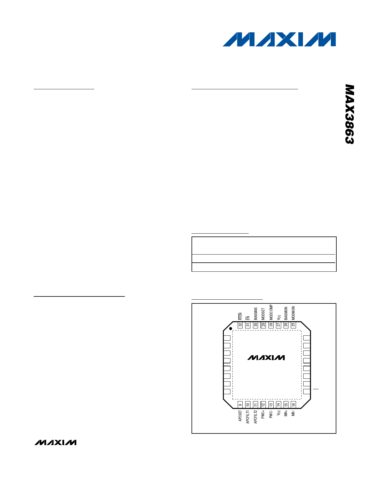
Pin Configuration
TOP VIEW
VCC 1
DATA+ 2
DATA- 3
VCC 4
VCC 5
CLK+ 6
CLK- 7
VCC 8
MAX3863
24 MDMON
23 MD
22 VCC
21 MODN
20 MOD
19 VCC
18 BIAS
17 FAIL
Covered by U.S. patent number 5,883,910. Other patents
pending.
THE EXPOSED PAD MUST BE SOLDERED TO GND ON THE CIRCUIT BOARD.
________________________________________________________________ Maxim Integrated Products 1
For pricing, delivery, and ordering information, please contact Maxim/Dallas Direct! at
1-888-629-4642, or visit Maxim’s website at www.maxim-ic.com.
1 page 
2.7Gbps Laser Driver with Modulation
Compensation
Typical Operating Characteristics (continued)
(TA = +25°C, unless otherwise noted. See Typical Operating Circuit.)
MODULATION CURRENT vs.
MODULATION SET RESISTOR
100
10
1
0.1
300
1 10
RMODSET (kΩ)
BIAS MONITOR VOLTAGE
vs. BIAS CURRENT
100
250
200
150
100
50
0
0 10 20 30 40 50 60 70 80 90 100
IBIAS (mA)
COMPENSATION (K)
vs. RMODCOMP
10
1
0.1
0.01
0.01
0.1 1 10
RMODCOMP (kΩ)
100
MODULATION MONITOR VOLTAGE
vs. MODULATION CURRENT
200
180
160
140
120
100
80
60
40
20
0
5 20 35 50 65 80
IMOD (mA)
MONITOR DIODE CURRENT
vs. APCSET RESISTOR
10
1
0.1
0.01
0.1
1 10 100
RAPCSET (kΩ)
1000
POWER-SUPPLY NOISE REJECTION
vs. FREQUENCY
120
100
80
60
40
20
0
0.1 1 10 100 1000 10,000
FREQUENCY (kHz)
BIAS CURRENT
vs. BIASMAX SET RESISTOR
1000
100
10
1
0.1
1 10
RBIASMAX (kΩ)
100
DIODE-CURRENT MONITOR VOLTAGE
vs. MONITOR DIODE CURRENT
3.0
2.5
2.0
1.5
1.0
0.5
0
0 0.5 1.0 1.5 2.0 2.5
IMD (mA)
SINGLE-ENDED S11 vs. FREQUENCY
0
-5
-10
-15
-20
-25
-30
-35
-40
0
1234
FREQUENCY (GHz)
5
_______________________________________________________________________________________ 5
5 Page 
2.7Gbps Laser Driver with Modulation
Compensation
LASER
POWER
IMOD1
IMOD2
VCC
P1
PAVG
T1
T2
DATA+
DATA-
50Ω
50Ω
P0
IBIAS1
IBIAS2 LASER CURRENT
Figure 4. Laser Power vs. Current for a Change in Temperature
GND
Figure 5. Equivalent Input Circuit
IMOD = IMODS + K × IBIAS
I MODS
=
200
×
1.2V
R MODSET
K = 200 ×
5
500 + R MODCOMP
VCC MOD MODN GND
Applications Information
Layout Considerations
To minimize loss and crosstalk, keep connections
between the MAX3863 output and the laser diode as
short as possible. Use good high-frequency layout
techniques and multilayer boards with uninterrupted
ground plane to minimize EMI and crosstalk. Circuit
boards should be made using low-loss dielectrics. Use
controlled-impedance lines for the clock and data
inputs, as well as the module output.
Laser Safety and IEC 825
Using the MAX3863 laser driver alone does not ensure
that a transmitter design is compliant with IEC825. The
entire transmitter circuit and component selections
must be considered. Determine the level of fault toler-
ance required by each application and recognize that
Maxim products are not designed or authorized for use
as components in systems intended for surgical im-
plant into the body, for applications intended to support
or sustain life, or for any other application where the
IMOD
GND
Figure 6. Equivalent Output Circuit
failure of a Maxim product could create a situation
where personal injury or death may occur.
______________________________________________________________________________________ 11
11 Page | ||
| Páginas | Total 15 Páginas | |
| PDF Descargar | [ Datasheet MAX3863.PDF ] | |
Hoja de datos destacado
| Número de pieza | Descripción | Fabricantes |
| MAX3861 | 2.7Gbps Post Amp with Automatic Gain Control | Maxim Integrated |
| MAX3863 | 2.7Gbps Laser Driver | Maxim Integrated Products |
| MAX3864 | 2.5Gbps / +3V to +5.5V / Wide Dynamic Range Transimpedance Preamplifier | Maxim Integrated |
| MAX3865 | 2.5Gbps Laser Driver with Automatic Modulation Control | Maxim Integrated |
| Número de pieza | Descripción | Fabricantes |
| SLA6805M | High Voltage 3 phase Motor Driver IC. |
Sanken |
| SDC1742 | 12- and 14-Bit Hybrid Synchro / Resolver-to-Digital Converters. |
Analog Devices |
|
DataSheet.es es una pagina web que funciona como un repositorio de manuales o hoja de datos de muchos de los productos más populares, |
| DataSheet.es | 2020 | Privacy Policy | Contacto | Buscar |