|
|
|
PDF XRT73R12 Data sheet ( Hoja de datos )
| Número de pieza | XRT73R12 | |
| Descripción | TWELVE CHANNEL E3/DS3/STS-1 LINE INTERFACE UNIT | |
| Fabricantes | Exar Corporation | |
| Logotipo | ||
Hay una vista previa y un enlace de descarga de XRT73R12 (archivo pdf) en la parte inferior de esta página. Total 30 Páginas | ||
|
No Preview Available !
www.DataSheet4U.com
PRELIMINARY
XRT73R12
TWELVE CHANNEL E3/DS3/STS-1 LINE INTERFACE UNIT
OCTOBER 2003
GENERAL DESCRIPTION
The XRT73R12 is a twelve channel fully integrated
Line Interface Unit (LIU) featuring EXAR’s R3
Technology (Reconfigurable, Relayless Redundancy)
for E3/DS3/STS-1 applications. The LIU incorporates
12 independent Receivers and Transmitters in a
single 420 Lead TBGA package.
Each channel of the XRT73R12 can be
independently configured to operate in E3 (34.368
MHz), DS3 (44.736 MHz) or STS-1 (51.84 MHz).
Each transmitter can be turned off and tri-stated for
redundancy support or for conserving power.
The XRT73R12’s differential receiver provides high
noise interference margin and is able to receive data
over 1000 feet of cable or with up to 12 dB of cable
attenuation.
REV. P1.0.3
The XRT73R12 provides a Parallel Microprocessor
Interface for programming and control.
The XRT73R12 supports analog, remote and digital
loop-backs. The device also has a built-in Pseudo
Random Binary Sequence (PRBS) generator and
detector with the ability to insert and detect single bit
error for diagnostic purposes.
APPLICATIONS
• E3/DS3 Access Equipment
• DSLAMs
• Digital Cross Connect Systems
• CSU/DSU Equipment
• Routers
• Fiber Optic Terminals
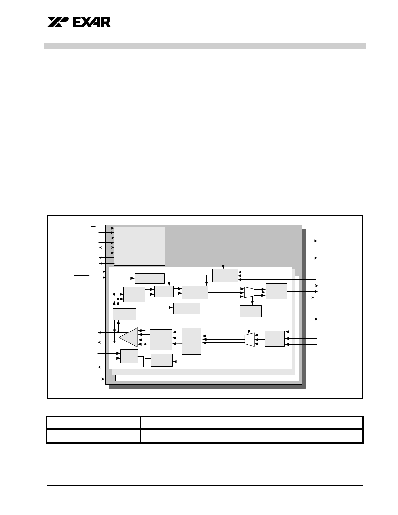
FIGURE 1. BLOCK DIAGRAM OF THE XRT 73R12
CS
RD
WR
Addr[7:0]
D[7:0]
PCLK
RDY
INT
Pmode
RESET
RTIP_n
RRing_n
TTIP_n
TRing_n
MTIP_n
MRing_n
DMO_n
ICT
µProcessor Interface
XRT73R12
Peak Detector
AGC/
Equalizer
Slicer
Local
LoopBack
Clock & Data
Recovery
LOS
Detector
Clock
Synthesizer
MUX
Remote
LoopBack
HDB3/
B3ZS
Decoder
Line
Driver
Device
Monitor
Tx
Pulse
Shaping
Tx
Control
Timing
Control
HDB3/
MUX B3ZS
Encoder
Channel 0
Channel n...
Channel 11
CLKOUT_n
SFM_en
RLOL_n
E3Clk
DS3Clk
STS-Clk/12M
RxClk_n
RxPOS_n
RxNEG/LCV_n
RLOS_n
TxClk_n
TxPOS_n
TxNEG_n
TxON
PART NUMBER
XRT73R12IB
ORDERING INFORMATION
PACKAGE
420 Lead TBGA
OPERATING TEMPERATURE RANGE
-40°C to +85°C
Exar Corporation 48720 Kato Road, Fremont CA, 94538 • (510) 668-7000 • FAX (510) 668-7017 • www.exar.com
1 page 
PRELIMINARY
XRT73R12
TWELVE CHANNEL E3/DS3/STS-1 LINE INTERFACE UNIT
REV. P1.0.3
TABLE 23: CHANNEL LEVEL INTERRUPT STATUS REGISTER - CR225 (ADDRESS LOCATION = 0XE1)....................................................... 63
TABLE 24: DEVICE/PART NUMBER REGISTER - CR110 (ADDRESS LOCATION = 0X6E) ........................................................................... 64
TABLE 25: CHIP REVISION NUMBER REGISTER - CR111 (ADDRESS LOCATION = 0X6F) ......................................................................... 64
THE PER-CHANNEL REGISTERS........................................................................................................................... 65
REGISTER DESCRIPTION - PER CHANNEL REGISTERS .................................................................................... 66
TABLE 26: XRT73R12 REGISTER MAP SHOWING INTERRUPT ENABLE REGISTERS (IER_N).................................................................. 66
TABLE 27: SOURCE LEVEL INTERRUPT ENABLE REGISTER - CHANNEL N ADDRESS LOCATION = 0XM1 .................................................... 66
TABLE 28: XRT73R12 REGISTER MAP SHOWING INTERRUPT STATUS REGISTERS (ISR_N).................................................................. 68
TABLE 29: SOURCE LEVEL INTERRUPT STATUS REGISTER - CHANNEL N ADDRESS LOCATION = 0XM2 .................................................... 68
TABLE 30: XRT73R12 REGISTER MAP SHOWING ALARM STATUS REGISTERS (AS_N) .......................................................................... 70
TABLE 31: ALARM STATUS REGISTER - CHANNEL N ADDRESS LOCATION = 0XM3................................................................................... 70
TABLE 32: XRT73R12 REGISTER MAP SHOWING TRANSMIT CONTROL REGISTERS (TC_N)................................................................... 73
TABLE 33: TRANSMIT CONTROL REGISTER - CHANNEL N ADDRESS LOCATION = 0XM4 ........................................................................... 73
TABLE 34: XRT73R12 REGISTER MAP SHOWING RECEIVE CONTROL REGISTERS (RC_N) .................................................................... 75
TABLE 35: RECEIVE CONTROL REGISTER - CHANNEL N ADDRESS LOCATION = 0XM5 ............................................................................. 75
TABLE 36: XRT73R12 REGISTER MAP SHOWING CHANNEL CONTROL REGISTERS (CC_N) ................................................................... 76
TABLE 37: CHANNEL CONTROL REGISTER - CHANNEL N ADDRESS LOCATION = 0XM6 ............................................................................ 76
TABLE 38: XRT73R12 REGISTER MAP SHOWING ERROR COUNTER MSBYTE REGISTERS (EM_N)........................................................ 79
TABLE 39: ERROR COUNTER MSBYTE REGISTER - CHANNEL N ADDRESS LOCATION = 0XMA................................................................. 79
TABLE 40: XRT73R12 REGISTER MAP SHOWING ERROR COUNTER LSBYTE REGISTERS (EL_N).......................................................... 79
TABLE 41: ERROR COUNTER LSBYTE REGISTER - CHANNEL N ADDRESS LOCATION = 0XMB.................................................................. 80
TABLE 42: XRT73R12 REGISTER MAP SHOWING ERROR COUNTER HOLDING REGISTERS (EH_N) ........................................................ 80
TABLE 43: ERROR COUNTER HOLDING REGISTER - CHANNEL N ADDRESS LOCATION = 0XMC ................................................................ 81
8.0 ELECTRICAL CHARACTERISTICS ................................................................................................... 82
TABLE 44: ABSOLUTE MAXIMUM RATINGS ............................................................................................................................................. 82
TABLE 45: DC ELECTRICAL CHARACTERISTICS:..................................................................................................................................... 82
ORDERING INFORMATION .................................................................................................................. 83
PACKAGE DIMENSIONS - .............................................................................................................................................. 83
REVISIONS .................................................................................................................................................................. 84
III
5 Page 
PRELIMINARY
TWELVE CHANNEL E3/DS3/STS-1 LINE INTERFACE UNIT
XRT73R12
REV. P1.0.3
RECEIVE LINE SIDE PINS
PIN #
SIGNAL NAME
TYPE
B22
AE22
B18
AE18
A14
AF14
D13
AC13
B9
AE9
B5
AE5
RTip0
RTip1
RTip2
RTip3
RTip4
RTip5
RTip6
RTip7
RTip8
RTip9
RTip10
RTip11
I
C22
AD22
C18
AD18
B14
AE14
C13
AD13
C9
AD9
C5
AD5
RRing0
RRing1
RRing2
RRing3
RRing4
RRing5
RRing6
RRing7
RRing8
RRing9
RRing10
RRing11
I
DESCRIPTION
Receive TIP Input
These input pins along with the corresponding RRing_n input pin function as the
Receive DS3/E3/STS-1 Line input signal for a given channel of the XRT73R12.
Cconnect this signal and the corresponding RRING_n input signal to a 1:1
transformer.
Whenever the RTIP/RRING input pins are receiving a positive-polarity pulse
within the incoming DS3, E3 or STS-1 line signal, this input pin will be pulsed to
a higher voltage than its corresponding RRING_n input pin.
Conversely, whenever the RTIP/RRING input pins are receiving a negative-
polarity pulse within the incoming DS3, E3 or STS-1 line signal, this input pin
will be pulsed to a lower voltage than its corresponding RRING_n input pin.
Receive Ring Input
These input pins along with the corresponding RTIP_n input pin function as the
Receive DS3/E3/STS-1 Line input signal for a given channel of the XRT73R12.
Connect this signal and the corresponding RTIP_n input signal to a 1:1 trans-
former. (See Figure 6)
Whenever the RTIP/RRING input pins are receiving a positive-polarity pulse
within the incoming DS3, E3 or STS-1 line signal, then this input pin will be
pulsed to a lower voltage than its corresponding RTIP_n input pin.
Conversely, whenever the RTIP/RRING input pins are receiving a negative-
polarity pulse within the incoming DS3, E3 or STS-1 line signal, then this input
pin will be pulsed to a higher voltage than its corresponding RTIP_n input pin.
8
11 Page | ||
| Páginas | Total 30 Páginas | |
| PDF Descargar | [ Datasheet XRT73R12.PDF ] | |
Hoja de datos destacado
| Número de pieza | Descripción | Fabricantes |
| XRT73R12 | TWELVE CHANNEL E3/DS3/STS-1 LINE INTERFACE UNIT | Exar Corporation |
| Número de pieza | Descripción | Fabricantes |
| SLA6805M | High Voltage 3 phase Motor Driver IC. |
Sanken |
| SDC1742 | 12- and 14-Bit Hybrid Synchro / Resolver-to-Digital Converters. |
Analog Devices |
|
DataSheet.es es una pagina web que funciona como un repositorio de manuales o hoja de datos de muchos de los productos más populares, |
| DataSheet.es | 2020 | Privacy Policy | Contacto | Buscar |