|
|
|
PDF MA4TD1110 Data sheet ( Hoja de datos )
| Número de pieza | MA4TD1110 | |
| Descripción | Silicon Bipolar MMIC Cascadable Amplifier | |
| Fabricantes | M-pulse Microwave | |
| Logotipo | ||
Hay una vista previa y un enlace de descarga de MA4TD1110 (archivo pdf) en la parte inferior de esta página. Total 3 Páginas | ||
|
No Preview Available !
www.DataSheet4U.com
M-Pulse Microwave
Silicon Bipolar MMIC
Cascadable Amplifier
MP4TD1110
Features
• High Dynamic Range Cascadable 50Ω/75Ω Gain Block
• 3dB Bandwidth: 50 MHz to 1.3 GHz
• 17.0 dBm Typical P1dB @ 1.0 GHz
• 12 dB Typical Gain @ 0.5 GHz
• 3.8 dB Typical Noise Figure @ 1.0 GHz
• Hermetic Gold-Ceramic Microstrip Package
• Tape and Reel Packaging Available
Description
M-Pulse's MP4TD1110 is a high performance silicon
bipolar MMIC housed in a hermetic high reliability
package. The MP4TD1110 is designed for use in
systems where a high dynamic range and low distortion
gain block is required. Typical applications include
narrow and wide band IF and RF amplifiers in industrial
and military applications.
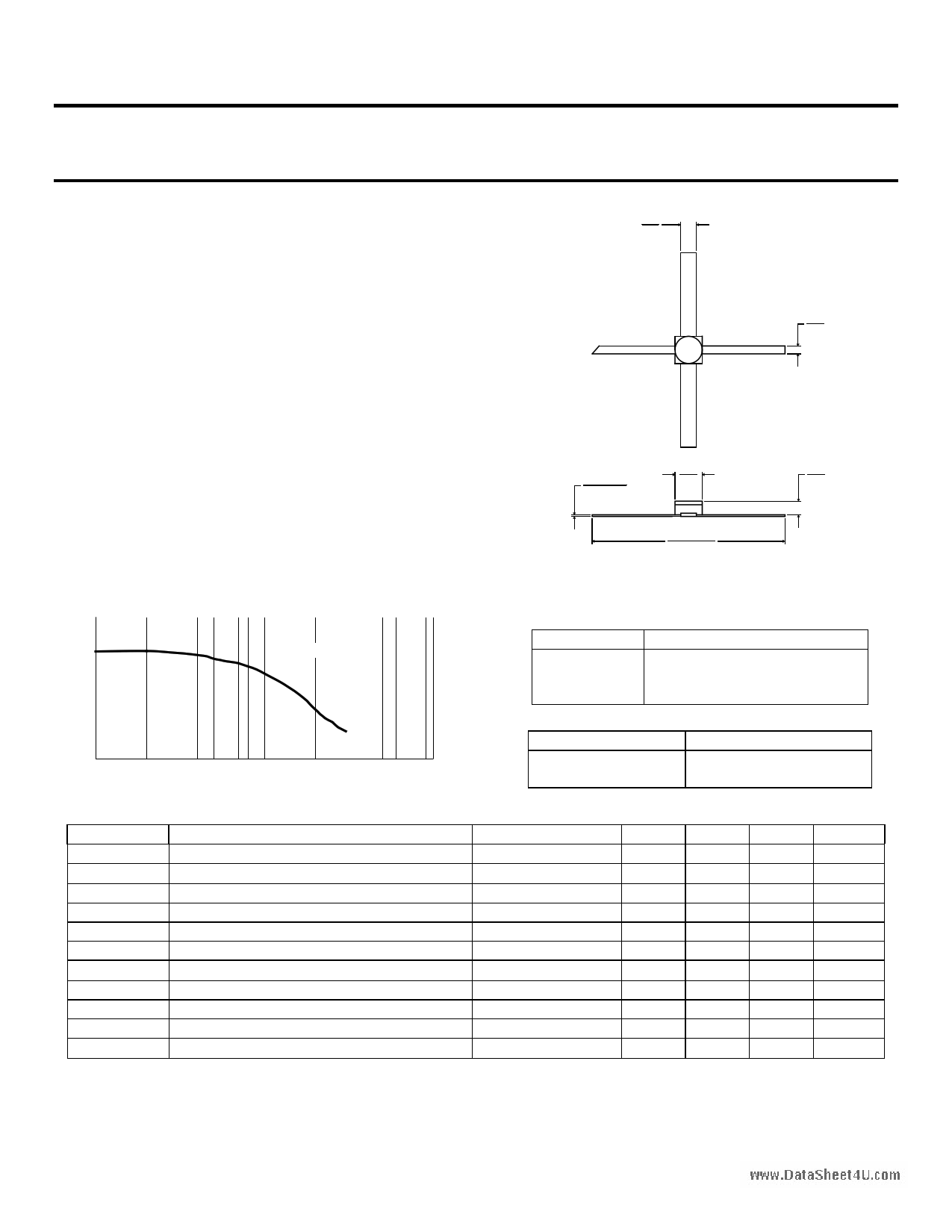
Gold-Ceramic Microstrip Package Outline1,2
.040
1,02
4 GND
RF INPUT
1
RF OUT
AND BIAS
3
.020
0,51
.004 ±.002
0,1±0,05
2 GND
.100
2,54
.030
0,76
The MP4TD1110 is fabricated using a 10 GHz fT silicon
bipolar technology that features gold metalization and IC
passivation for increased performance and reliability.
TYPICAL POWER GAIN vs FREQUENCY
16
14
Id=60mA
12
10
8
6
4
2
0.1
1
FREQUENCY (GHz)
10
.495 ±.030
12,57 ±0,76
Notes: (unless otherwise specified)
1. Dimensions are in / mm
2. Tolerance: in .xxx = ±.005; mm .xx = ±.13
Pin Configuration
Pin Number
Pin Description
1 RF Input
2&4
AC/DC Ground
3 RF Output and DC Bias
Ordering Information
Model No.
MA4TD1110
MA4TD1110T
Package
Hermetic Ceramic
Tape and Reel
Electrical Specifications @ TA = +25°C, Id = 60 mA, Z0 = 50Ω
Symbol Parameters
Test Conditions
Gp
ΔGp
Power Gain (⏐S21⏐2)
Gain Flatness
f = 0.1 GHz
f = 0.1 to 0.7 GHz
f3dB 3 dB Bandwidth
ref 50 MHz Gain
SWRin Input SWR
f = 0.1 to 2.0 GHz
SWRout Output SWR
f = 0.1 to 2.0 GHz
P1dB
Output Power @ 1 dB Gain Compression f = 0.7 GHz
NF 50 Ω Noise Figure
f = 0.7 GHz
IP3 Third Order Intercept Point
f = 1.0 GHz
tD Group Delay
f = 1.0 GHz
Vd Device Voltage
-
dV/dT Device Voltage Temperature Coefficient
-
Units
dB
dB
GHz
-
-
dBm
dB
dBm
ps
V
mV/°C
Min.
11.5
-
-
-
-
16.0
-
-
-
4.5
-
Typ.
12.5
±0.8
1.3
1.9
2.1
17.0
3.8
30.0
160
5.5
-8.0
Max.
13.5
±1.0
-
-
-
-
4.5
-
-
6.5
-
Specification Subject to Change Without Notice
M-Pulse Microwave __________________________________________________________________________________
PH (408) 432-1480 FX (408) 432-3440
1
1 page | ||
| Páginas | Total 3 Páginas | |
| PDF Descargar | [ Datasheet MA4TD1110.PDF ] | |
Hoja de datos destacado
| Número de pieza | Descripción | Fabricantes |
| MA4TD1110 | Silicon Bipolar MMIC Cascadable Amplifier | M-pulse Microwave |
| Número de pieza | Descripción | Fabricantes |
| SLA6805M | High Voltage 3 phase Motor Driver IC. |
Sanken |
| SDC1742 | 12- and 14-Bit Hybrid Synchro / Resolver-to-Digital Converters. |
Analog Devices |
|
DataSheet.es es una pagina web que funciona como un repositorio de manuales o hoja de datos de muchos de los productos más populares, |
| DataSheet.es | 2020 | Privacy Policy | Contacto | Buscar |