|
|
|
PDF MAX13036 Data sheet ( Hoja de datos )
| Número de pieza | MAX13036 | |
| Descripción | Automotive Contact Monitor and Level Shifter | |
| Fabricantes | Maxim Integrated Products | |
| Logotipo | ||
Hay una vista previa y un enlace de descarga de MAX13036 (archivo pdf) en la parte inferior de esta página. Total 18 Páginas | ||
|
No Preview Available !
19-0808; Rev 0; 4/07
EVAALVUAAILTAIOBNLEKIT
Automotive Contact Monitor
and Level Shifter
General Description
The MAX13036 automotive contact monitor and level
shifter monitors and debounces eight remote mechanical
switches and asserts an interrupt (INT) if a switch
changes state. The state of each switch is sampled
through an SPI™ interface by reading the status register
and any switch can be prohibited from asserting an inter-
rupt by writing to the command register. Four of the
switch inputs are intended for ground-connected switch-
es (IN0–IN3), and the other four inputs (IN4–IN7), are
programmable in groups of two for either ground-con-
nected or battery-connected switches. Two switch inputs
(IN0, IN1) have direct level-shifted outputs (DO0, DO1)
to be used for PWM or other timing-based signals.
Switch input thresholds are set to 50% of the voltage
applied to BATREF. The threshold hysteresis is set by
connecting an external resistor from HYST to ground.
The MAX13036 supplies an adjustable wetting current to
each closed switch to clean mechanical switch contacts
that are exposed to adverse conditions.
The MAX13036 operates with a +6V to +26V battery volt-
age applied to BAT. A separate +2.7V to +5.5V logic sup-
www.DataSheet4U.com ply input (VL) sets the interface voltage. The MAX13036 is
available in a 5mm x 5mm 28-pin TQFN package and
operates over the -40°C to +125°C temperature range.
Body Computers
Window Lifters
Seat Movers
Applications
Electric Sunroofs
Other Control ECUs
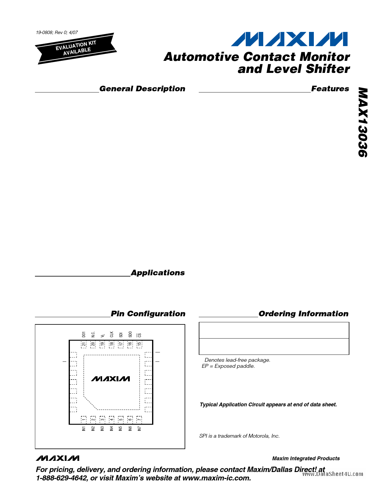
Pin Configuration
TOP VIEW
DO0 22
SD 23
GND 24
BATREF 25
BAT 26
N.C. 27
INO 28
*EP
+
MAX13036
14 INT
13 OT
12 GND
11 TDEB
10 WET
9 HYST
8 N.C.
Features
o +6V to +26V Operating Voltage Range
o +42V Compatibility on BAT
o Inputs Withstand Reverse Battery
o Withstands Dynamic Battery Voltage Drop While
VL is Present
o Ultra-Low Operating Current 17µA (typ) in
Scan Mode
o Resistor-Adjustable Switching Hysteresis
o CMOS-Compatible Logic Outputs (+2.7V min)
o Built-In Switch Debouncing
o Interrupt Output
o Immunity to Transients
o High Modularity
o Thermal Protection
o ±8kV HBM ESD Protection on IN0–IN7 Without
External Components
o Two Inputs (IN0, IN1) Programmable as Direct
Outputs
o Four Inputs (IN4–IN7) Programmable for BAT or
GND Related Switches
Ordering Information
PART
TEMP RANGE
PIN-
PACKAGE
PKG
CODE
MAX13036ATI+
-40°C to +125°C
28 TQFN-EP*
(5mm x 5mm)
T2855-8
+ Denotes lead-free package.
*EP = Exposed paddle.
Typical Application Circuit appears at end of data sheet.
TQFN
*CONNECT EXPOSED PADDLE TO GROUND
SPI is a trademark of Motorola, Inc.
________________________________________________________________ Maxim Integrated Products 1
For pricing, delivery, and ordering information, please contact Maxim/Dallas Direct! at
1-888-629-4642, or visit Maxim’s website at www.maxim-ic.com.
1 page 
Automotive Contact Monitor
and Level Shifter
Test Circuits/Timing Diagrams
CS
tLEAD
CLK
tSI(SU) tSI(HOLD)
SDI MSB IN
tSO(EN)
SDO MSB OUT
tVALID
Figure 1. SPI Timing Characteristics
www.DataSheet4U.com
MAX13036
CS SDO
VL
1kΩ
15pF
CS
SDO
tSO(EN)
1/3VL
Figure 2. SDO Enable/Disable Test Circuit and Timing Diagram
tLAG
tSO(DIS)
LSB OUT
tSO(DIS)
VOL + 0.1VL
_______________________________________________________________________________________ 5
5 Page 
Automotive Contact Monitor
and Level Shifter
Wetting Current (WET)
The MAX13036 features adjustable wetting current to
any closed switch to clean switch contacts that are
exposed to adverse conditions. The wetting current is
set by connecting a 30kΩ to 330kΩ resistor from WET
to ground. A 30kΩ resistor corresponds to a wetting
current of 40mA (typ) and a 330kΩ resistor corre-
sponds to a 7.5mA (typ) wetting current. See the
Typical Operating Characteristics section for the rela-
tionship between the wetting current and RWET.
The WEN and WEND bits in the command register
enable and disable the wetting currents and the WTOFF
bit allows the wetting current to be activated for a dura-
tion of 20ms (typ) (see the Command Register section).
Disabling wetting currents, or limiting the active wetting
current time reduces power consumption. The default
state upon power-up is all wetting currents disabled.
Wetting current is activated on closed switches just
after the debounce time. The wetting current pulse
starts after the debounce time. A wetting current pulse
is provided to all closed switches when a valid input
change is detected. Wetting current rise and fall times
are controlled to enhance EMC performance. There is
onewww.DataSheet4U.com wetting current timer for all switch inputs.
Therefore, it is possible to observe wetting pulses
longer than expected whenever two switches turn on in
sequence and are spaced out less than tWET. In scan
mode, the wetting current is enabled during the polling
pulse only.
When using wetting currents, special care must be taken
to avoid exceeding the maximum power dissipation of the
MAX13036 (see the Applications Information section).
Switch Outputs (DO0, DO1)
DO0 and DO1 are direct level-shifted outputs of the
switch inputs IN0 and IN1 when the WEND bit of the
command register is cleared and when operating in
normal mode. When configured as direct inputs, the
wetting currents and sensing resistors are disabled on
IN0 and IN1. DO0 and DO1 are tri-stated when the
WEND bit is set or when operating in scan mode.
When programmed as direct inputs, the status of IN0
and IN1 are not reflected in the status register and
interrupts are not allowed on these inputs.
Interrupt Output (INT)
INT is an active-low, open-drain output that asserts
when any of the switch inputs changes state, as long
as the particular input is enabled for interrupts (set by
clearing P7–P0 in the command register). A pullup
resistor to VL is needed on INT. INT is cleared when CS
is driven low for a read/write operation.
The INT output will still assert when VL is absent provid-
ed that it is pulled up to a different supply voltage.
Thermal Protection (OT)
The MAX13036 features thermal protection that pre-
vents the device from being damaged by overheating.
When the internal temperature of the device exceeds
the thermal warning threshold of +170°C (typ), all wet-
ting currents are disabled. The MAX13036 returns to
normal operation after the internal temperature
decreases below +155°C (typ). The thermal shutdown
does not activate below +150°C. The thermal protec-
tion feature is disabled when WEN = 0 or when all
inputs are open.
An open-drain, active-low output (OT) asserts low when
the internal temperature of the device rises above the
thermal warning threshold. OT is immediately cleared
when the CS input is driven low for write/read opera-
tions, regardless of whether the temperature is above
the threshold or not. The overtemperature status of the
MAX13036 can also be monitored by reading the OT bit
in the status register. The OT bit is set when the internal
temperature rises above the temperature threshold and
it is cleared when the temperature falls below the tem-
perature hysteresis level. This allows a microprocessor
(µP) to monitor the overtemperature status, even if the
OT output has been cleared. See Figure 4 for an exam-
ple timing diagram of the overtemperature alerts.
If desired, the OT and INT outputs can be connected to
the same µP GPIO in a wired-OR configuration to save a
µP pin. The OT output still asserts when VL is absent
provided that it is pulled up to a different supply voltage.
Serial Peripheral Interface
(CS, SD0, SDI, CLK)
The MAX13036 operates as a Serial Peripheral Interface
(SPI) slave device. An SPI master accesses the
MAX13036 by reading from a status register and writing
to a command register. Both registers are 16 bits long
and are accessed most significant bit (MSB) first.
TEMPERATURE
OT
CS
OT BIT
Figure 4. Example Timing Diagram of the Overtemperature Alerts
______________________________________________________________________________________ 11
11 Page | ||
| Páginas | Total 18 Páginas | |
| PDF Descargar | [ Datasheet MAX13036.PDF ] | |
Hoja de datos destacado
| Número de pieza | Descripción | Fabricantes |
| MAX1303 | (MAX1302 / MAX1303) Serial 16-Bit ADCs | Maxim Integrated Products |
| MAX13030E | (MAX13030E - MAX13035E) 6-Channel High SPeed LLT | Maxim Integrated Products |
| MAX13031E | (MAX13030E - MAX13035E) 6-Channel High SPeed LLT | Maxim Integrated Products |
| MAX13032E | (MAX13030E - MAX13035E) 6-Channel High SPeed LLT | Maxim Integrated Products |
| Número de pieza | Descripción | Fabricantes |
| SLA6805M | High Voltage 3 phase Motor Driver IC. |
Sanken |
| SDC1742 | 12- and 14-Bit Hybrid Synchro / Resolver-to-Digital Converters. |
Analog Devices |
|
DataSheet.es es una pagina web que funciona como un repositorio de manuales o hoja de datos de muchos de los productos más populares, |
| DataSheet.es | 2020 | Privacy Policy | Contacto | Buscar |