|
|
|
PDF AD8099 Data sheet ( Hoja de datos )
| Número de pieza | AD8099 | |
| Descripción | Voltage Noise Op Amp | |
| Fabricantes | Analog Devices | |
| Logotipo | ||
1. AD8099 Hay una vista previa y un enlace de descarga de AD8099 (archivo pdf) en la parte inferior de esta página. Total 27 Páginas | ||
|
No Preview Available !
Data Sheet
Ultralow Distortion, High Speed,
0.95 nV/√Hz Voltage Noise Op Amp
AD8099
FEATURES
Ultralow noise: 0.95 nV/√Hz, 2.6 pA/√Hz
Ultralow distortion
2nd harmonic RL = 1 kΩ , G = +2
−92 dB at 10 MHz
3rd harmonic RL = 1 kΩ , G = +2
−105 dB at 10 MHz
High speed
Gain bandwidth product (GBWP): 3.8 GHz
−3 dB bandwidth
700 MHz (G = +2)
550 MHz (G = +10)
Slew rate
475 V/µs (G = +2)
1350 V/µs (G = +10)
New pinout
Custom external compensation, gain range –1, +2 to +10
Supply current: 15 mA
Offset voltage: 0.5 mV max
Wide supply voltage range: 5 V to 12 V
APPLICATIONS
Preamplifiers
Receivers
Instrumentation
Filters
Intermediate frequency (IF) and baseband amplifiers
Analog-to-digital drivers
Digital-to-analog converter (DAC) buffers
Optical electronics
GENERAL DESCRIPTION
The AD8099 is an ultralow noise (0.95 nV/√Hz) and distortion
(–92 dBc at 10 MHz) voltage feedback op amp, the combination
of which makes it ideal for 16- and 18-bit systems. The AD8099
features a new, highly linear, low noise input stage that increases
the full power bandwidth (FPBW) at low gains with high slew
rates. The Analog Devices, Inc., proprietary next generation
extra fast complimentary bipolar (XFCB) process enables such
high performance amplifiers with relatively low power.
The AD8099 features external compensation, which lets the user
set the gain bandwidth product. External compensation allows
gains from +2 to +10 with minimal trade-off in bandwidth. The
AD8099 also features an extremely high slew rate of 1350 V/µs,
giving the designer flexibility to use the entire dynamic range
without trading off bandwidth or distortion. The AD8099
settles to 0.1% in 18 ns and recovers from overdrive in 50 ns.
Rev. E
Document Feedback
Information furnished by Analog Devices is believed to be accurate and reliable. However, no
responsibilityisassumedbyAnalogDevices for itsuse,nor foranyinfringementsofpatentsor other
rights of third parties that may result from its use. Specifications subject to change without notice. No
license is granted by implication or otherwise under any patent or patent rights of Analog Devices.
Trademarksandregisteredtrademarksarethepropertyoftheirrespectiveowners.
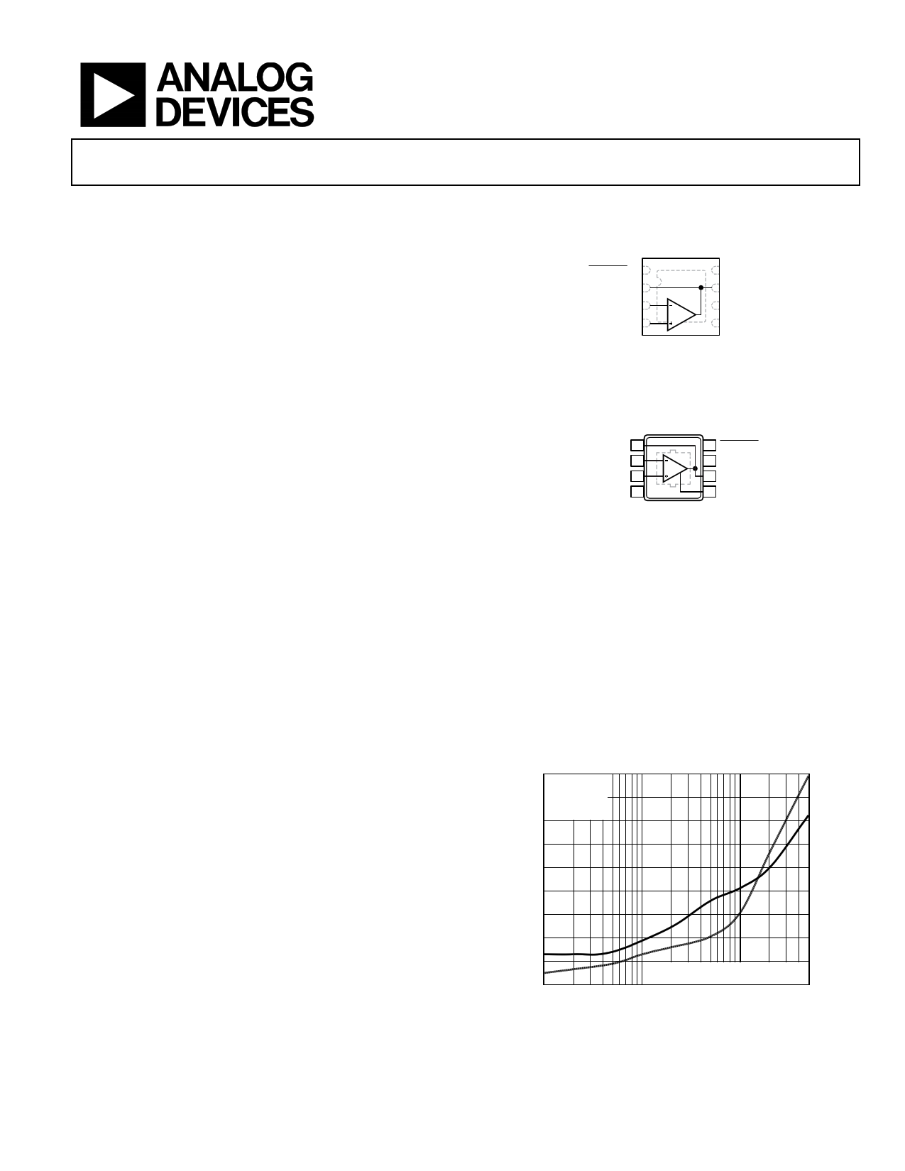
CONNECTION DIAGRAMS
AD8099
TOP VIEW
(Not to Scale)
DISABLE 1
FEEDDBACK 2
–IN 3
+IN 4
8 +VS
7 VOUT
6 CC
5 –VS
NOTES
1. SOLDER THE EXPOSED PADDLE
TO THE GROUND PLANE.
Figure 1. 8-Lead LFCSP (CP-8-13)
AD8099
TOP VIEW
(Not to Scale)
FEEDBACK 1
8 DISABLE
–IN 2
+IN 3
–VS 4
7 +VS
6 VOUT
5 CC
NOTES
1. SOLDER THE EXPOSED PADDLE
TO THE GROUND PLANE.
Figure 2. 8-Lead SOIC-EP (RD-8-1)
The AD8099 drives 100 Ω loads at breakthrough performance
levels with only 15 mA of supply current. With the wide supply
voltage range (5 V to 12 V), low offset voltage (0.1 mV typ), wide
bandwidth (700 MHz for G = +2), and a GBWP up to 3.8 GHz,
the AD8099 is designed to work in a wide variety of applications.
The AD8099 is available in a 3 mm × 3 mm lead frame chip scale
package (LFCSP) with a new pinout that is specifically optimized
for high performance, high speed amplifiers. The new LFCSP and
pinout enable the breakthrough performance that previously was
not achievable with amplifiers. The AD8099 is rated to work
over the extended industrial temperature range, −40°C to +125°C.
–40
G = +2
–50
VOUT = 2V p-p
VS = ±5V
RL = 1kΩ
–60
–70
–80
–90
–100
–110
–120
–130
0.1
SOLID LINE – SECOND HARMONIC
DOTTED LINE – THIRD HARMONIC
1.0 10.0
FREQUENCY (MHz)
Figure 3. Harmonic Distortion vs. Frequency and Gain (SOIC)
One Technology Way, P.O. Box 9106, Norwood, MA 02062-9106, U.S.A.
Tel: 781.329.4700 ©2003–2016 Analog Devices, Inc. All rights reserved.
Technical Support
www.analog.com
1 page 
AD8099
Data Sheet
SPECIFICATIONS WITH +5 V SUPPLY
VS = 5 V at TA = 25°C, G = +2, RL = 1 kΩ to midsupply, unless otherwise noted. Refer to Figure 60 through Figure 66 for component
values and gain configurations.
Table 2.
Parameter
DYNAMIC PERFORMANCE
−3 dB Bandwidth
Bandwidth for 0.1 dB Flatness (SOIC/LFCSP)
Slew Rate
Settling Time to 0.1%
NOISE/DISTORTION PERFORMANCE
Harmonic Distortion (dBc) HD2/HD3
Input Voltage Noise
Input Current Noise
DC PERFORMANCE
Input Offset Voltage
Input Offset Voltage Drift
Input Bias Current
Input Bias Offset Current
Input Bias Offset Current Drift
Open-Loop Gain
INPUT CHARACTERISTICS
Input Resistance
Input Capacitance
Input Common-Mode Voltage Range
Common-Mode Rejection Ratio
DISABLE PIN
DISABLE Input Voltage
Turn-Off Time
Turn-On Time
Enable Pin Leakage Current
DISABLE Pin Leakage Current
OUTPUT CHARACTERISTICS
Overdrive Recovery Time (Rise/Fall)
Output Voltage Swing
Short-Circuit Current
Off Isolation
POWER SUPPLY
Operating Range
Quiescent Current
Quiescent Current (Disabled)
Positive Power Supply Rejection Ratio
Negative Power Supply Rejection Ratio
Test Conditions/Comments
Min Typ
G = +5, VOUT = 0.2 V p-p
G = +5, VOUT = 2 V p-p
G = +2, VOUT = 0.2 V p-p
G = +10, VOUT = 2 V Step
G = +2, VOUT = 2 V Step
G = +2, VOUT = 2 V Step
fC = 500 kHz, VOUT = 1 V p-p, G = +10
fC = 10 MHz, VOUT = 1 V p-p, G = +10
f = 100 kHz
f = 100 kHz, DISABLE pin floating
f = 100 kHz, DISABLE pin = +VS
415 440
165 210
33/23
630 715
340 365
18
−82/−94
−80/−75
0.95
2.6
5.2
DISABLE pin floating
DISABLE pin = +VS
VOUT = 1 V to 4 V
Differential mode
Common mode
VCM = 2 V to 3 V
0.1
2.5
−6.2
−0.2
0.05
2.4
76 81
4
10
2
1.3 to 3.7
88 105
Output disabled
50% of DISABLE to <10% of Final VOUT,
VIN = 0.5 V, G = +2
50% of DISABLE to <10% of Final VOUT,
VIN = 0.5 V, G = +2
DISABLE = 5 V
DISABLE = 0 V
<2.4
105
61
16
33
VIN = 0 to 2.5 V, G = +2
RL = 100 Ω
RL = 1 kΩ
Sinking and Sourcing
f = 1 MHz, DISABLE = Low
1.5 to 3.5
1.2 to 3.8
50/70
1.2 to 3.8
1.2 to 3.8
60/80
−61
DISABLE = Low
+VS = 4.5 V to 5.5 V, −VS = 0 V (input referred)
+VS =5 V, −VS= −0.5 V to +0.5 V (input referred)
84
84
±5
14.5
1.4
89
90
Max Unit
MHz
MHz
MHz
V/µs
V/µs
ns
dBc
dBc
nV/√Hz
pA/√Hz
pA/√HZ
0.5 mV
µV/°C
−13 µA
−2 µA
1 µA
nA/°C
dB
kΩ
MΩ
pF
V
dB
V
ns
ns
21 µA
44 µA
ns
V
V
mA
dB
±6 V
15.4 mA
1.7 mA
dB
dB
Rev. E | Page 4 of 26
5 Page 
AD8099
–50
G = +10
RL = 1kΩ
–60
–70
VS = ±2.5V
VOUT = 1V p-p
–80
–90
–100
–110
VS = ±5V
VOUT = 2V p-p
–120
0.1
SOLID LINES – SECOND HARMONICS
DOTTED LINES – THIRD HARMONICS
1.0 10.0
FREQUENCY (MHz)
Figure 29. Harmonic Distortion vs. Frequency and Supply Voltage (SOIC)
–40
G = +5
VS = ±5V
–50 f = 10MHz
RL = 100Ω
–60
–70
–80
–90
–100
–110
1
SOLID LINE – SECOND HARMONIC
DOTTED LINE – THIRD HARMONIC
2345
OUTPUT AMPLITUDE (V p-p)
6
7
Figure 30. Harmonic Distortion vs. Output Amplitude (SOIC)
–40
G = +5
VS = ±5V
–50 f = 10MHz
RL = 1kΩ
–60
–70
–80
–90
–100
–110
–120
1
SOLID LINE – SECOND HARMONIC
DOTTED LINE – THIRD HARMONIC
234567
OUTPUT AMPLITUDE (V p-p)
Figure 31. Harmonic Distortion vs. Output Amplitude (SOIC)
Data Sheet
–50
G = +10
RL = 1kΩ
–60
–70
VS = ±2.5V
VOUT = 1V p-p
–80
–90
–100
–110
VS = ±5V
VOUT = 2V p-p
–120
0.1
SOLID LINES – SECOND HARMONICS
DOTTED LINES– –THTHIRIRDDHHAARRMMOONNICICSS
1.0 10.0
FREQUENCY (MHz)
Figure 32. Harmonic Distortion vs. Frequency for Various Supplies (LFCSP
–40
G = +5
VS = ±5V
–50 f = 10MHz
RL = 100Ω
–60
–70
–80
–90
–100
–110
1
SOLID LINE – SECOND HARMONIC
DOTTED LINE – THIRD HARMONIC
2345
OUTPUT AMPLITUDE (V p-p)
6
7
Figure 33. Harmonic Distortion vs. Output Amplitude (LFCSP)
–40
G = +5
VS = ±5V
–50 f = 10MHz
RL = 1kΩ
–60
–70
–80
–90
–100
–110
–120
1
SOLID LINE – SECOND HARMONIC
DOTTED LINE – THIRD HARMONIC
234567
OUTPUT AMPLITUDE (V p-p)
Figure 34. Harmonic Distortion vs. Output Amplitude (LFCSP)
Rev. E | Page 10 of 26
11 Page | ||
| Páginas | Total 27 Páginas | |
| PDF Descargar | [ Datasheet AD8099.PDF ] | |
Hoja de datos destacado
| Número de pieza | Descripción | Fabricantes |
| AD809 | 155.52 MHz Frequency Synthesizer | Analog Devices |
| AD8091 | (AD8091 / AD8092) High Speed Rail-to-Rail Amplifiers | Analog Devices |
| AD8092 | (AD8091 / AD8092) High Speed Rail-to-Rail Amplifiers | Analog Devices |
| AD8099 | Voltage Noise Op Amp | Analog Devices |
| Número de pieza | Descripción | Fabricantes |
| SLA6805M | High Voltage 3 phase Motor Driver IC. |
Sanken |
| SDC1742 | 12- and 14-Bit Hybrid Synchro / Resolver-to-Digital Converters. |
Analog Devices |
|
DataSheet.es es una pagina web que funciona como un repositorio de manuales o hoja de datos de muchos de los productos más populares, |
| DataSheet.es | 2020 | Privacy Policy | Contacto | Buscar |