|
|
|
PDF IRG4PSH71K Data sheet ( Hoja de datos )
| Número de pieza | IRG4PSH71K | |
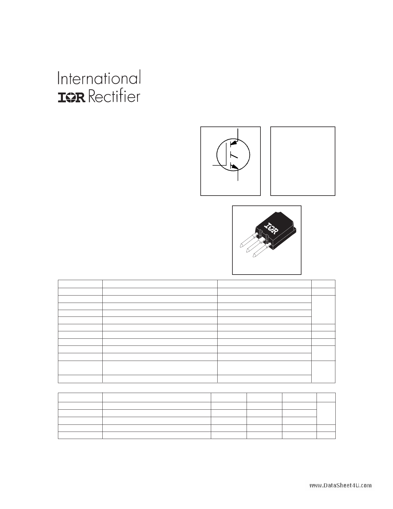
| Descripción | INSULATED GATE BIPOLAR TRANSISTOR | |
| Fabricantes | International Rectifier | |
| Logotipo | ||
Hay una vista previa y un enlace de descarga de IRG4PSH71K (archivo pdf) en la parte inferior de esta página. Total 8 Páginas | ||
|
No Preview Available !
PD - 91687A
PRELIMINARY
INSULATED GATE BIPOLAR TRANSISTOR
IRG4PSH71K
Short Circuit Rated
UltraFast IGBT
Features
• Hole-less clip/pressure mount package compatible
with TO-247 and TO-264, with reinforced pins
• High short circuit rating IGBTs, optimized for
motorcontrol
• Minimum switching losses combined with low
conduction losses
• Tightest parameter distribution
• Creepage distance increased to 5.35mm
C
G
E
n-channel
VCES = 1200V
VCE(on) typ. = 2.97V
@VGE = 15V, IC = 42A
Benefits
• Highest current rating IGBT
• Maximum power density, twice the power
handling of the TO-247, less space than TO-264
Absolute Maximum Ratings
VCES
IC @ TC = 25°C
IC @ TC = 100°C
ICM
ILM
tSC
VGE
EARV
PD @ TC = 25°C
PD @ TC = 100°C
TJ
TSTG
Parameter
Collector-to-Emitter Breakdown Voltage
Continuous Collector Current
Continuous Collector Current
Pulsed Collector Current
Clamped Inductive Load Current
Short Circuit Withstand Time
Gate-to-Emitter Voltage
Reverse Voltage Avalanche Energy
Maximum Power Dissipation
Maximum Power Dissipation
Operating Junction and
Storage Temperature Range
Soldering Temperature, for 10 seconds
Thermal Resistance\ Mechanical
RθJC
RθCS
RθJA
www.irf.com
Parameter
Junction-to-Case
Case-to-Sink, flat, greased surface
Junction-to-Ambient, typical socket mount
Recommended Clip Force
Weight
SUPER - 247
Max.
1200
78
42
156
156
10
± 20
170
350
140
-55 to + 150
300 (0.063 in. (1.6mm from case )
Units
V
A
µs
V
mJ
W
°C
Min.
–––
–––
–––
20.0(2.0)
–––
Typ.
–––
0.24
–––
–––
6 (0.21)
Max.
0.36
–––
38
–––
–––
Units
°C/W
N (kgf)
g (oz)
1
5/11/99
1 page 
IRG4PSH71K
10000
8000
VGE = 0V, f = 1MHz
Cies = Cge + Cgc , Cce SHORTED
Cres = Cgc
Coes = Cce + Cgc
6000
Cies
4000
2000
0
1
Coes
Cres
10 100
VCE , Collector-to-Emitter Voltage (V)
Fig. 7 - Typical Capacitance vs.
Collector-to-Emitter Voltage
20 VCC = 400V
I C = 42A
15
10
5
0
0 100 200 300 400 500
QG , Total Gate Charge (nC)
Fig. 8 - Typical Gate Charge vs.
Gate-to-Emitter Voltage
20
VCC = 960V
VGE = 15V
TJ = 25 °C
IC = 42A
15
10
100 RG = 5.0 Ω
VGE = 15V
VCC = 960V
10
IC = 84A
IC = 42A
IC = 21A
5
0 10 20 30 40 50
RG , Gate Resistance Ω
Fig. 9 - Typical Switching Losses vs. Gate
Resistance
www.irf.com
1
-60 -40 -20 0 20 40 60 80 100 120 140 160
TJ , Junction Temperature (° C )
Fig. 10 - Typical Switching Losses vs.
Junction Temperature
5
5 Page | ||
| Páginas | Total 8 Páginas | |
| PDF Descargar | [ Datasheet IRG4PSH71K.PDF ] | |
Hoja de datos destacado
| Número de pieza | Descripción | Fabricantes |
| IRG4PSH71K | INSULATED GATE BIPOLAR TRANSISTOR | International Rectifier |
| IRG4PSH71KD | INSULATED GATE BIPOLAR TRANSISTOR | International Rectifier |
| IRG4PSH71KDPBF | INSULATED GATE BIPOLAR TRANSISTOR | International Rectifier |
| IRG4PSH71U | INSULATED GATE BIPOLAR TRANSISTOR | International Rectifier |
| Número de pieza | Descripción | Fabricantes |
| SLA6805M | High Voltage 3 phase Motor Driver IC. |
Sanken |
| SDC1742 | 12- and 14-Bit Hybrid Synchro / Resolver-to-Digital Converters. |
Analog Devices |
|
DataSheet.es es una pagina web que funciona como un repositorio de manuales o hoja de datos de muchos de los productos más populares, |
| DataSheet.es | 2020 | Privacy Policy | Contacto | Buscar |