|
|
|
PDF ICM7218 Data sheet ( Hoja de datos )
| Número de pieza | ICM7218 | |
| Descripción | 8-Digit LED Microprocessor-Compatible Multiplexed Display Decoder Driver | |
| Fabricantes | Intersil Corporation | |
| Logotipo | ||
Hay una vista previa y un enlace de descarga de ICM7218 (archivo pdf) en la parte inferior de esta página. Total 11 Páginas | ||
|
No Preview Available !
Data Sheet
September 15, 2015
ICM7218
FN3159.3
8-Digit LED Microprocessor-Compatible
Multiplexed Display Decoder Driver
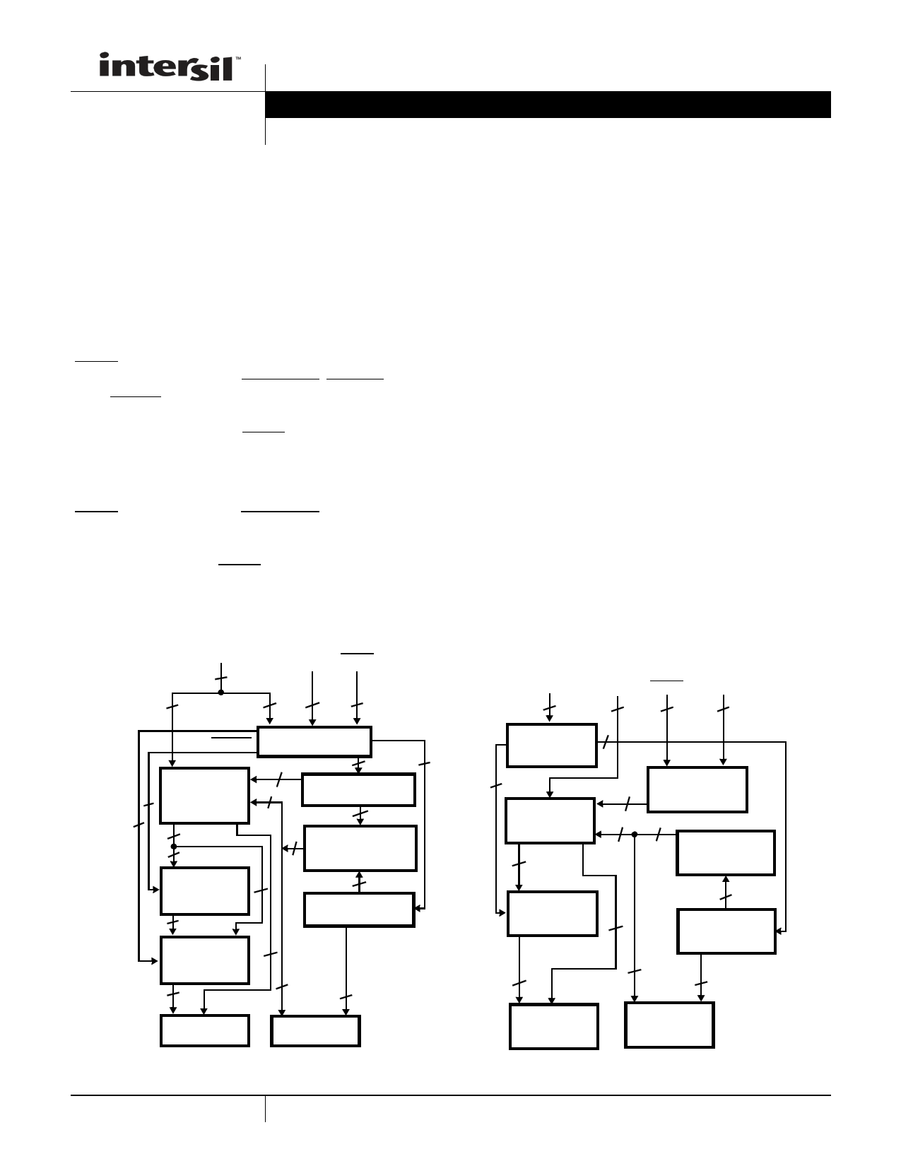
The ICM7218 series of universal LED driver systems
provide, in a single package, all the circuitry necessary to
interface most common microprocessors or digital systems
to an LED display. Included on chip are an 8-byte static
display memory, two types of 7-segment decoders, multiplex
scan circuitry, and high current digit and segment drivers for
either common-cathode or common-anode displays.
The lCM7218A and 1CM7218B feature two control lines
(WRITE and MODE) which write either 4 bits of control
information (DATA COMING, SHUTDOWN, DECODE, and
HEXA/CODE B) or 8 bits of display input data. Display data
is automatically sequenced into the 8-byte internal memory
on successive positive going WRITE pulses. Data may be
displayed either directly or decoded in Hexadecimal or Code
B formats.
The ICM7218C and lCM7218D feature two control lines
(WRITE and HEXA/CODE B/SHUTDOWN), 4 separate
display data input lines, and 3 digit address lines. Display
data is written into the internal memory by setting up a digit
address and strobing the WRITE line low. Only Hexadecimal
and Code B formats are available for display outputs.
Features
• Microprocessor Compatible
• Total Circuit Integration On Chip Includes:
- Digit and Segment Drivers
- All Multiplex Scan Circuitry
- 8-Byte Static Display Memory
- 7-Segment Hexadecimal and Code B Decoders
• Output Drive Suitable for LED Displays Directly
• Common Anode and Common Cathode Versions
• Single 5V Supply Required
• Data Retention to 2V Supply
• Shutdown Feature - Turns Off Display and Puts Chip Into
Low Power Dissipation Mode
• Sequential and Random Access Versions
• Decimal Point Drive On Each Digit
Related Literature
• Technical Brief TB363 “Guidelines for Handling and
Processing Moisture Sensitive Surface Mount Devices
(SMDs)”
ID0-ID7
INPUT
DATA
8
ICM7218A COMMON ANODE
ICM7218B COMMON CATHODE
ID4-ID7 MODE WRITE
8 CONTROL
INPUTS
41
1
1
1
7
4
DECODE
HEXA/CODE B
8-BYTE
STATIC
RAM
CONTROL
SHUTDOWN
LOGIC
81
1
WRITE ADDRESS
8 COUNTER
1
8
READ
ADRESS, DIGIT
MULTIPLEXER
HEXADECIMAL/
CODE B
7
DECODER
7
3
MULTIPLEX
OSCILLATOR
DECODE/
NO-DECODE
1
7 DECIMAL
POINT
8-SEGMENT
DRIVERS
1
8
8-DIGIT
DRIVERS
INTERDIGIT
BLANKING
ICM7218C COMMON ANODE
ICM7218D COMMON CATHODE
HEXADECIMAL/
CODE B/
SHUTDOWN
1
ID0-ID3
ID7
DATA
INPUT
5
WRITE
1
DA0-DA2
DIGIT
ADDRESS
3
THREE LEVEL 1
INPUT LOGIC
1
8-BYTE
STATIC
RAM
4
8
8
SHUTDOWN
WRITE
ADDRESS
DECODER
8
READ
ADRESS
MULTIPLEXER
HEXADECIMAL/
CODE B
DECODER
1
8
7 DECIMAL
POINT
5
MULTIPLEX
OSCILLATOR
1 INTERDIGIT
BLANKING
8-SEGMENT
DRIVERS
8-DIGIT
DRIVERS
FIGURE 1. FUNCTIONAL DIAGRAMS
1 CAUTION: These devices are sensitive to electrostatic discharge; follow proper IC Handling Procedures.
1-888-INTERSIL or 1-888-468-3774 | Copyright Intersil Americas LLC 2001, 2007, 2015. All Rights Reserved
Intersil (and design) and XDCP are trademarks owned by Intersil Corporation or one of its subsidiaries.
All other trademarks mentioned are the property of their respective owners.
1 page 
ICM7218
FIGURE 2. MULTIPLEX TIMING (COMMON CATHODE VERSION)
sign (-), a blank (for leading zero blanking), certain useful
alpha characters and all numeric formats.
The four bit binary code is set up on inputs lD3-lD0, and
decimal point data is set up on ID7.
FIGURE 3. SEGMENT ASSIGNMENTS
Detailed Description
DECODE Operation
For the lCM7218A/B products, there are 3 input data formats
possible; either direct segment and decimal point information (8
bits per digit) or two Binary formats plus decimal point
information (Hexadecimal/Code B formats with 5 bits per digit).
The 7-segment decoder on chip is disabled when direct
segment information is to be written. In this format, the
inputs directly control the outputs as follows:
Input Data:
Output Segments:
ID7 lD6 ID5 lD4 lD3 lD2 lD1 ID0
D.P. a b c e g f d
Here, "Ones" represent "on" segments for all inputs except
the Decimal Point. For the Decimal Point "zero" represents
an "on" segment.
HEXAdecimal/CODE B Decoding
For all products, a choice of either HEXA or Code B decoding
may be made. HEXA decoding provides 7-segment numeric
plus six alpha characters while Code B provides a negative
DECIMAL 0 1 2 3 4 5 6 7 8 9 10 11 12 13 14 15
HEXA
CODE
01234567 8 9 A B C D E
F
CODE B 0 1 2 3 4 5 6 7 8 9 - E H L P (BLANK)
SHUTDOWN
SHUTDOWN performs several functions: it puts the device
into a very low dissipation mode (typically 10A at VDD = 5V),
turns off both the digit and segment drivers, and stops the
multiplex scan oscillator (this is the only way the scan
oscillator can be disabled). However, it is still possible to input
data to the memory during shutdown - only the display output
sections of the device are disabled in this mode.
Powerdown
In the Shutdown Mode, the supply voltage may be reduced to
2V without data in memory being lost. However, data should
not be written into memory if the supply voltage is less than 4V.
Output Drive
The common anode output drive is approximately 200mA per
digit at a 12% duty cycle. With segment peak drive current of
40mA typically, this results in 5mA average drive. The common
cathode drive capability is approximately one-half that of the
common anode drive. If high impedance LED displays are
used, the drive current will be correspondingly less.
5 FN3159.3
September 15, 2015
5 Page 
ICM7218
Ceramic Dual-In-Line Frit Seal Packages (CERDIP)
BASE
PLANE
SEATING
PLANE
S1
b2
c1 LEAD FINISH
-A- -D-
BASE
METAL
(c)
E
b1
MM
-B- (b)
bbb S C A - B S D S
SECTION A-A
D
Q
-C- A
L
AA
eA
be
eA/2
c
ccc M C A - B S D S
aaa M C A - B S D S
NOTES:
1. Index area: A notch or a pin one identification mark shall be locat-
ed adjacent to pin one and shall be located within the shaded
area shown. The manufacturer’s identification shall not be used
as a pin one identification mark.
2. The maximum limits of lead dimensions b and c or M shall be
measured at the centroid of the finished lead surfaces, when
solder dip or tin plate lead finish is applied.
3. Dimensions b1 and c1 apply to lead base metal only. Dimension
M applies to lead plating and finish thickness.
4. Corner leads (1, N, N/2, and N/2+1) may be configured with a
partial lead paddle. For this configuration dimension b3 replaces
dimension b2.
5. This dimension allows for off-center lid, meniscus, and glass
overrun.
6. Dimension Q shall be measured from the seating plane to the
base plane.
7. Measure dimension S1 at all four corners.
8. N is the maximum number of terminal positions.
9. Dimensioning and tolerancing per ANSI Y14.5M - 1982.
10. Controlling dimension: INCH.
F28.6 MIL-STD-1835 GDIP1-T28 (D-10, CONFIGURATION A)
28 LEAD CERAMIC DUAL-IN-LINE FRIT SEAL PACKAGE
INCHES
MILLIMETERS
SYMBOL MIN MAX MIN MAX NOTES
A
- 0.232 - 5.92
-
b
0.014
0.026
0.36
0.66
2
b1
0.014
0.023
0.36
0.58
3
b2
0.045
0.065
1.14
1.65
-
b3
0.023
0.045
0.58
1.14
4
c
0.008
0.018
0.20
0.46
2
c1
0.008
0.015
0.20
0.38
3
D
-
1.490
- 37.85
5
E
0.500
0.610 12.70
15.49
5
e 0.100 BSC
2.54 BSC
-
eA 0.600 BSC
15.24 BSC
-
eA/2
0.300 BSC
7.62 BSC
-
L
0.125
0.200
3.18
5.08
-
Q
0.015
0.060
0.38
1.52
6
S1 0.005 - 0.13
-
7
90o 105o 90o 105o
-
aaa
- 0.015 - 0.38
-
bbb
- 0.030 - 0.76
-
ccc
- 0.010 - 0.25
-
M
-
0.0015
-
0.038
2, 3
N 28
28 8
Rev. 0 4/94
All Intersil U.S. products are manufactured, assembled and tested utilizing ISO9001 quality systems.
Intersil Corporation’s quality certifications can be viewed at www.intersil.com/design/quality
Intersil products are sold by description only. Intersil Corporation reserves the right to make changes in circuit design, software and/or specifications at any time without
notice. Accordingly, the reader is cautioned to verify that data sheets are current before placing orders. Information furnished by Intersil is believed to be accurate and
reliable. However, no responsibility is assumed by Intersil or its subsidiaries for its use; nor for any infringements of patents or other rights of third parties which may result
from its use. No license is granted by implication or otherwise under any patent or patent rights of Intersil or its subsidiaries.
For information regarding Intersil Corporation and its products, see www.intersil.com
11 FN3159.3
September 15, 2015
11 Page | ||
| Páginas | Total 11 Páginas | |
| PDF Descargar | [ Datasheet ICM7218.PDF ] | |
Hoja de datos destacado
| Número de pieza | Descripción | Fabricantes |
| ICM7211 | (ICM7211 / ICM7212) Four Digit Display Decoder/Drivers | Maxim Integrated Products |
| ICM7211 | (ICM7211 / ICM7212) 4-Digit LCD Display Driver | Harris Semiconductor |
| ICM7211A | 4-Digit LCD Display Driver | Intersil Corporation |
| ICM7211AM | 4-Digit LCD Display Driver | Intersil Corporation |
| Número de pieza | Descripción | Fabricantes |
| SLA6805M | High Voltage 3 phase Motor Driver IC. |
Sanken |
| SDC1742 | 12- and 14-Bit Hybrid Synchro / Resolver-to-Digital Converters. |
Analog Devices |
|
DataSheet.es es una pagina web que funciona como un repositorio de manuales o hoja de datos de muchos de los productos más populares, |
| DataSheet.es | 2020 | Privacy Policy | Contacto | Buscar |