|
|
|
PDF LA4460N Data sheet ( Hoja de datos )
| Número de pieza | LA4460N | |
| Descripción | (LA4460N / LA4461N) 12W AF Power Amplifier | |
| Fabricantes | Sanyo Semicon Device | |
| Logotipo | ||
Hay una vista previa y un enlace de descarga de LA4460N (archivo pdf) en la parte inferior de esta página. Total 12 Páginas | ||
|
No Preview Available !
Ordering number:ENN2660B
Monolithic Linear IC
LA4460N, 4461N
12W AF Power Amplifier
for Car Radio, Car Stereo
Features
• High gain of 51dB typ. and high power output of 12W
typ.
• Possible to delete output and bootstrap capacitors, this
encourages cost and space reductions due to external parts
reduction.
• Reduced external components (8 pieces recommended, 6
pieces minimum).
• Almost no pop noises heard during power on or off op-
eration.
• Soft tonal quality in saturated power output.
• Low distortion over low to high ranges of the audio fre-
quencies.
• Low residual noises (Rg=0).
• Good operation conditions because of SIP (single ended
pins) package having been employed for the LA4460N.
• All pin terminal layouts of the LA4461N are reversed for
easy stereo PC board pattern arrengement.
• Two ground terminals for pre-amplifier and power ampli-
fier are provided for easy PC board pattern arrangement
www.DataSheet4U.com and for stabilizing distortion chracteristics depending on
signal source impedance.
• Voltage gain is fixed at 51dB, however, lowering the gain
is possible by adding a resistor.
• IC is not damaged, if it is connected reversely.
• Audio muting functions (AC mute & DC mute) are
equipped.
• Several protection circuits are installed, including :
a. Thermal protection circuit.
b. Overvoltage & surge voltage protection circuit.
c. Load short-circuit current limiting protection circuit.
d. Output pins DC short-circuit protection circuit.
(grounding protection between OUT & GND, and
speaker protection provided.)
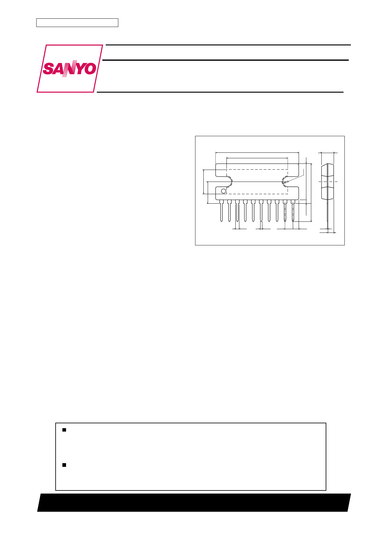
Package Dimensions
unit:mm
3024A-SIP10H
[LA4460N, 4461N]
27.0
20.0
4.0
1
1.4
10
0.5 2.54
2.07
0.4
2.0
SANYO : SIP10H
Any and all SANYO products described or contained herein do not have specifications that can handle
applications that require extremely high levels of reliability, such as life-support systems, aircraft’s
control systems, or other applications whose failure can be reasonably expected to result in serious
physical and/or material damage. Consult with your SANYO representative nearest you before using
any SANYO products described or contained herein in such applications.
SANYO assumes no responsibility for equipment failures that result from using products at values that
exceed, even momentarily, rated values (such as maximum ratings, operating condition ranges,or other
parameters) listed in products specifications of any and all SANYO products described or contained
herein.
SANYO Electric Co.,Ltd. Semiconductor Company
TOKYO OFFICE Tokyo Bldg., 1-10, 1 Chome, Ueno, Taito-ku, TOKYO, 110-8534 JAPAN
21500TN (KT)/90196RM/D187KI, TS No.2660–1/12
1 page 
LA4460N, 4461N
c) Starting time adjustment resistor RX
The purpose of the RX is to adjust the starting time ts, and a resistor of 1.5kΩ is used. In this case, a rising DC locus
as shown below will be obtained at the output terminals.
The circuit has been set to provide signals about 0.4µs. after the power is turned on. Though the ts will increase with
decreasing RX, the total output across the load will be decreased, since the signal flowing to the non-inverted side will
flow into the ground through the RX. Contrarily, increasing the RX to RX=∞ as shown in the Sample Application
Circuit 2, the ts reduces to zero s., and the rising locus as shown below will be obtained.
d) Oscillation compensation CR across the load
To prevent parasitic oscillation, it is recommended to connect 0.033µF plus 4.7Ω between each channel output termi-
nal and GND. (As a rule the capacitor should be a polyester film capacitor.) This measure against the oscillation may
be replaced with the methods as shown below, depending upon the stability of PC boards used.
Note :
· Check for oscillation at low temperatures.
· Check for oscillation on stereo PC boards.
· Do not use shielded wires for output cords.
Note :
· Check for oscillation at low temperatures.
· Use 8Ω load resistor.
· Do not use shielded wires for output cords.
· L should be higher than 0.3µH.
(Removal of oscillation compensation CR)
Coil used
Air core
Inner diameter : 8ø
Number of turns : 6 turns
Wire size : UEW 1.5 Winding method : Solenoid (0.3µH)
Above examples can be applied to the Sample Application Circuits 1, 2.
Features of IC System and Roles of the Remaining Pin Terminals
· Since a zero-bias design is introduced into the input circuit to keep the input potential at about zero by employing PNP
in the input circuit, an input coupling capacitor can be removed for direct connection. However, when noises caused by
a DC current flowing to a volume control circuit or the input circuit causes problems, connect a capacitor in series with
the input circuit.
· To prevent damage or deterioration of the IC due to the load short-circuited, a load short-circuit current limiting type
protection circuit has been provided.
However, when making the load short-circuit test, always mount the IC on the specified heat sink.
· A circuit which prevents pop noise caused by the power on-off operation is also provided, thereby reducing the offset
voltage and protecting speaker systems against damage.
Continued on next page.
No.2660–5/12
5 Page 
Sample Application Circuit 3 :
LA4460N, 4461N
Note ) In case where the LA3161 is used,
Rb and Cb must be changed. (Refer
to the LA3161 catalog.)
Example of oscillation compensation where feedthrough capacitors and used at the output terminals.
Coil used :
Air core
Inner diameter : 8ø
Number of turns : 6 turns
Wire size : UEW 1.5
Winding method : solenoid (0.3µH)
Connect each coil, L1 and L2, in series with each output terminal, where L1=L2.
No.2660–11/12
11 Page | ||
| Páginas | Total 12 Páginas | |
| PDF Descargar | [ Datasheet LA4460N.PDF ] | |
Hoja de datos destacado
| Número de pieza | Descripción | Fabricantes |
| LA4460 | 12W AF Power Amplifier For Car Radio or Car Stereo | Sanyo |
| LA4460N | (LA4460N / LA4461N) 12W AF Power Amplifier | Sanyo Semicon Device |
| Número de pieza | Descripción | Fabricantes |
| SLA6805M | High Voltage 3 phase Motor Driver IC. |
Sanken |
| SDC1742 | 12- and 14-Bit Hybrid Synchro / Resolver-to-Digital Converters. |
Analog Devices |
|
DataSheet.es es una pagina web que funciona como un repositorio de manuales o hoja de datos de muchos de los productos más populares, |
| DataSheet.es | 2020 | Privacy Policy | Contacto | Buscar |