|
|
|
PDF T5750 Data sheet ( Hoja de datos )
| Número de pieza | T5750 | |
| Descripción | UHF ASK/FSK Transmitter | |
| Fabricantes | ATMEL Corporation | |
| Logotipo | ||
Hay una vista previa y un enlace de descarga de T5750 (archivo pdf) en la parte inferior de esta página. Total 13 Páginas | ||
|
No Preview Available !
Features
• Integrated PLL Loop Filter
• ESD Protection also at ANT1/ANT2
(4 kV HBM/200V MM; Except Pin 2: 4 kV HBM/100V MM)
• High Output Power (5.5 dBm) with Low Supply Current (8.5 mA)
• Modulation Scheme ASK/FSK
– FSK Modulation is Achieved by Connecting an Additional Capacitor Between the
XTAL Load Capacitor and the Open Drain Output of the Modulating Microcontroller
• Easy to Design-in Due to Excellent Isolation of the PLL from the PA and Power Supply
• Single Li-cell for Power Supply
• Supply Voltage 2.0V to 4.0V in the Temperature Range of –40°C to +85°C/+125°C
• Package TSSOP8L
• Single-ended Antenna Output with High Efficient Power Amplifier
• CLK Output for Clocking the Microcontroller
• One-chip Solution with Minimum External Circuitry
• 125°C Operation for Tire Pressure Systems
UHF ASK/FSK
Transmitter
T5750
1. Description
The T5750 is a PLL transmitter IC which has been developed for the demands of RF
low-cost transmission systems at data rates up to 32 kBaud. The transmitting
frequency range is 868 MHz to 928 MHz. It can be used in both FSK and ASK
systems.
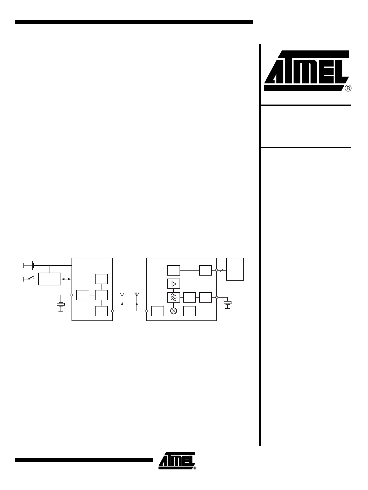
Figure 1-1.
1 Li cell
System Block Diagram
UHF ASK/FSK
Remote control transmitter
T5750
Keys
Encoder
ATARx9x
XTO
PLL
VCO
Antenna Antenna
www.DataSheet4U.com
UHF ASK/FSK
Remote control receiver
T5760/
T5761
Demod
Control
PLL XTO
1 to 3 Micro-
controller
LNA
LNA
VCO
4546E–RKE–02/07
1 page 
T5750
Figure 4-1. Tolerances of Frequency Modulation
VS
XTAL
CStray1
LM
CM
RS
CStray2
C4
C0 C5
CSwitch
Using C4 = 9.2 pF ±2%, C5 = 6.8 pF ±5%, a switch port with CSwitch = 3 pF ±10%, stray capaci-
tances on each side of the crystal of CStray1 = CStray2 = 1 pF ±10%, a parallel capacitance of the
crystal of C0 = 3.2 pF ±10% and a crystal with CM = 13 fF ±10%, an FSK deviation of ±21.5 kHz
typical with worst case tolerances of ±16.8 kHz to ±28.0 kHz results.
4.3 CLK Output
An output CLK signal is provided for a connected microcontroller, the delivered signal is CMOS
compatible if the load capacitance is lower than 10 pF.
4.3.1
Clock Pulse Take-over
The clock of the crystal oscillator can be used for clocking the microcontroller. Atmel®’s
ATARx9x has the special feature of starting with an integrated RC-oscillator to switch on the
T5750 with ENABLE = H, and after 4 ms to assume the clock signal of the transmission IC, so
that the message can be sent with crystal accuracy.
4.3.2
Output Matching and Power Setting
The output power is set by the load impedance of the antenna. The maximum output power is
achieved with a load impedance of ZLoad,opt = (166 + j226)Ω at 868.3 MHz. There must be a low
resistive path to VS to deliver the DC current.
The delivered current pulse of the power amplifier is 7.7 mA and the maximum output power is
delivered to a resistive load of 475Ω if the 0.53 pF output capacitance of the power amplifier is
compensated by the load impedance.
An optimum load impedance of:
ZLoad = 475Ω || j/(2 × p × f × 0.53 pF) = (166 + j226)Ω thus results for the maximum output
power of 5.5 dBm.
The load impedance is defined as the impedance seen from the T5750’s ANT1, ANT2 into the
matching network. Do not confuse this large signal load impedance with a small signal input
impedance delivered as input characteristic of RF amplifiers and measured from the application
into the IC instead of from the IC into the application for a power amplifier.
Less output power is achieved by lowering the real parallel part of 475Ω where the parallel imag-
inary part should be kept constant.
Output power measurement can be done with the circuit of Figure 4-2 on page 6. Note that the
component values must be changed to compensate the individual board parasitics until the
T5750 has the right load impedance ZLoad,opt = (166 + j226)Ω at 868.3 MHz. Also the damping of
the cable used to measure the output power must be calibrated out.
4546E–RKE–02/07
5
5 Page 
8. Ordering Information
Extended Type Number
T5750-6AQJ
9. Package Information
Package
TSSOP8L
Package: TSSOP 8L
Dimensions in mm
T5750
Remarks
Taped and reeled, Marking: T570, Pb-free
3±0.1
3±0.1
+0.06
0.31-0.07
0.65 nom.
3 x 0.65 = 1.95 nom.
8
5
Drawing-No.: 6.543-5083.01-4
Issue: 2; 15.03.04
14
3.8±0.3
4.9±0.1
technical drawings
according to DIN
specifications
4546E–RKE–02/07
11
11 Page | ||
| Páginas | Total 13 Páginas | |
| PDF Descargar | [ Datasheet T5750.PDF ] | |
Hoja de datos destacado
| Número de pieza | Descripción | Fabricantes |
| T5750 | UHF ASK/FSK Transmitter | ATMEL Corporation |
| T5753 | UHF ASK/FSK TRANSMITTER | ATMEL Corporation |
| T5754 | UHF ASK/FSK TRANSMITTER | ATMEL Corporation |
| Número de pieza | Descripción | Fabricantes |
| SLA6805M | High Voltage 3 phase Motor Driver IC. |
Sanken |
| SDC1742 | 12- and 14-Bit Hybrid Synchro / Resolver-to-Digital Converters. |
Analog Devices |
|
DataSheet.es es una pagina web que funciona como un repositorio de manuales o hoja de datos de muchos de los productos más populares, |
| DataSheet.es | 2020 | Privacy Policy | Contacto | Buscar |