|
|
|
PDF AAT3510 Data sheet ( Hoja de datos )
| Número de pieza | AAT3510 | |
| Descripción | (AAT3510 - AAT3519) Micropower uP Reset | |
| Fabricantes | AAT | |
| Logotipo | ||
Hay una vista previa y un enlace de descarga de AAT3510 (archivo pdf) en la parte inferior de esta página. Total 11 Páginas | ||
|
No Preview Available !
AAT3510/1/2/3/4/5/6/7/8/9
Micropower µP Reset with Watchdog Timer
General Description
Features
PoSwmearrMtSawnaitgcehr™™
The AAT351x PowerManager products are mem-
bers of AnalogicTech's Total Power Management
IC™ (TPMIC™) product family. This family of
microprocessor reset circuits provides the ultimate
in versatility, allowing system designers full cus-
tomization of the µP monitor and reset function
without any additional components. The AAT351x
family offers several combinations of threshold
voltage, watchdog timeout period, reset active peri-
od, and output drive configurations, which are all
factory-programmed options. All devices are avail-
able in 32 reset threshold voltages from 2.6V up to
5V, with three watchdog timeout periods from
6.3ms to 1600ms and three reset timeouts from
1ms up to 140ms. Available output configurations
are active low push-pull, active low open drain,
active low bi-directional, and active high push-pull.
• Tight Voltage Tolerance: ±1.5%
• Low Quiescent Current: 5µA
• Guaranteed Reset Valid Down to 1V
• 32 Voltage Options from 2.6V to 5.0V
• Three Reset Active Period Options:
— 1ms, 20ms, 140ms
• Three Watchdog Timeout Period Options:
— 6.3ms, 102ms, 1600ms
• Four Output Options:
— Open Drain
— Inverting
— Non-Inverting
— Bi-Directional
• Low Temperature Coefficient: 100ppm/°C
• 5-Pin SOT23 Package
The AAT351x family is designed to ignore fast neg-
ative transients on VDD and to ensure that reset
outputs remain valid down to 1V.
Applications
• Critical µP and µC Supply Monitoring
The AAT351x family is available in the Pb-free, •www.DataSheet4U.com Embedded Control Systems
space-saving 5-pin SOT23 surface mount package
• Industrial Controllers
and is specified over the -40 to +85°C temperature
• Intelligent Instruments
range.
• Notebook Computers
• Portable Electronics
• Power-On Reset Circuits
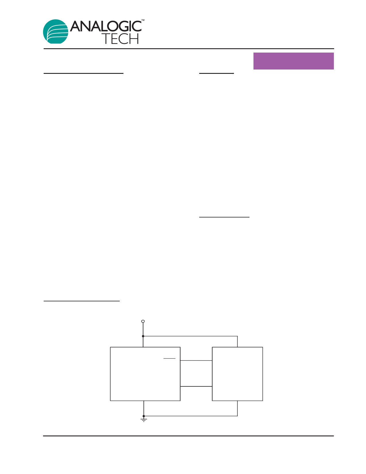
Typical Application
V DD
VCC
AAT351x
RESET
(RESET)
GND
WDI
RESET
INPUT
VDD
µP
I/O LINE
3510.2006.03.1.7
1
1 page 
AAT3510/1/2/3/4/5/6/7/8/9
Micropower µP Reset with Watchdog Timer
Electrical Characteristics
VCC = 2.5V to 5.5V, TA = -40°C to +85ºC1, unless otherwise noted. Typical values are at TA = 25°C.
Symbol Description
Conditions
Min
Open-Drain RESET Output (AAT3517, 3518, 3519)
VCC ≥ 1.0V, ISINK = 50µA
VOL RESET Low Output Voltage
VCC ≥ 1.2V, ISINK = 100µA
VCC ≥ 2.7V, ISINK = 1.2mA
VCC ≥ 4.5V, ISINK = 3.2mA
ID(OFF) Reset Leakage Current
Watchdog Input (AAT3510, 3511, 3512, 3513, 3514, 3517, 3518)
AAT351xIGV-xx-x-A-T1
tWD Watchdog Timeout Period
AAT351xIGV-xx-x-B-T1
AAT351xIGV-xx-x-C-T12
tWDI WDI Minimum Pulse Width
VIL = 0.3 x VCC, VIH = 0.7 x VCC
VIL WDI Input Threshold3
VIH WDI Input Threshold3
IWDI WDI Input Current4
WDI = VCC, Time Average
VWDI = 0, Time Average
Manual RESET Input (AAT3510, 3511, 3512, 3515, 3516, 3517, 3519)
VIL MR Input Threshold
MR Input Threshold
MR Input Pulse Width
VIH MR Glitch Rejection
MR Internal Pull-Up Resistance TA = 25°C
MR to Reset Delay
VCC = 5V
4.3
71
1.12
0.3 x VCC
-20
0.3 x VCC
1
35
Typ Max Units
0.3
0.3
0.3 V
0.4
1.0 µA
6.3 9.3
102 153
1.6 2.4
50
ms
s
ns
0.8 x VCC
120 160
-15
V
µA
0.7 x VCC
100
52 75
230
V
µs
ns
kΩ
ns
1. Over-temperature limits are guaranteed by design, not production tested.
2. Watchdog timeout period C is not available on AAT3513, AAT3514, and AAT3518.
3. WDI is internally serviced within the watchdog period if WDI is left unconnected.
4. The WDI input current is specified as the average input current when the WDI input is driven high or low. The WDI input is designed
for a three-stated-output device with a 10µA maximum leakage current and capable of driving a maximum capacitive load of 200pF.
The three-state device must be able to source and sink at least 200µA when active.
3510.2006.03.1.7
5
5 Page 
Package Information
2.85 ± 0.15
1.90 BSC
0.95
BSC
AAT3510/1/2/3/4/5/6/7/8/9
Micropower µP Reset with Watchdog Timer
SOT23-5
0.60 REF
10° ± 5°
All dimensions in millimeters.
0.075 ± 0.075
0.40 ± 0.10
0.60 REF
0.15 ± 0.07
GAUGE PLANE
0.45 ± 0.15
0.10 BSC
© Advanced Analogic Technologies, Inc.
AnalogicTech cannot assume responsibility for use of any circuitry other than circuitry entirely embodied in an AnalogicTech product. No circuit patent licenses, copyrights, mask work rights,
or other intellectual property rights are implied. AnalogicTech reserves the right to make changes to their products or specifications or to discontinue any product or service without notice.
Customers are advised to obtain the latest version of relevant information to verify, before placing orders, that information being relied on is current and complete. All products are sold
subject to the terms and conditions of sale supplied at the time of order acknowledgement, including those pertaining to warranty, patent infringement, and limitation of liability. AnalogicTech
warrants performance of its semiconductor products to the specifications applicable at the time of sale in accordance with AnalogicTech’s standard warranty. Testing and other quality con-
trol techniques are utilized to the extent AnalogicTech deems necessary to support this warranty. Specific testing of all parameters of each device is not necessarily performed.
Advanced Analogic Technologies, Inc.
830 E. Arques Avenue, Sunnyvale, CA 94085
Phone (408) 737-4600
Fax (408) 737-4611
3510.2006.03.1.7
11
11 Page | ||
| Páginas | Total 11 Páginas | |
| PDF Descargar | [ Datasheet AAT3510.PDF ] | |
Hoja de datos destacado
| Número de pieza | Descripción | Fabricantes |
| AAT3510 | (AAT3510 - AAT3519) Micropower uP Reset | AAT |
| AAT3511 | (AAT3510 - AAT3519) Micropower uP Reset | AAT |
| AAT3512 | (AAT3510 - AAT3519) Micropower uP Reset | AAT |
| AAT3513 | (AAT3510 - AAT3519) Micropower uP Reset | AAT |
| Número de pieza | Descripción | Fabricantes |
| SLA6805M | High Voltage 3 phase Motor Driver IC. |
Sanken |
| SDC1742 | 12- and 14-Bit Hybrid Synchro / Resolver-to-Digital Converters. |
Analog Devices |
|
DataSheet.es es una pagina web que funciona como un repositorio de manuales o hoja de datos de muchos de los productos más populares, |
| DataSheet.es | 2020 | Privacy Policy | Contacto | Buscar |