|
|
|
PDF NUP2105L Data sheet ( Hoja de datos )
| Número de pieza | NUP2105L | |
| Descripción | Dual Line CAN Bus Protector | |
| Fabricantes | ON Semiconductor | |
| Logotipo | ||
Hay una vista previa y un enlace de descarga de NUP2105L (archivo pdf) en la parte inferior de esta página. Total 8 Páginas | ||
|
No Preview Available !
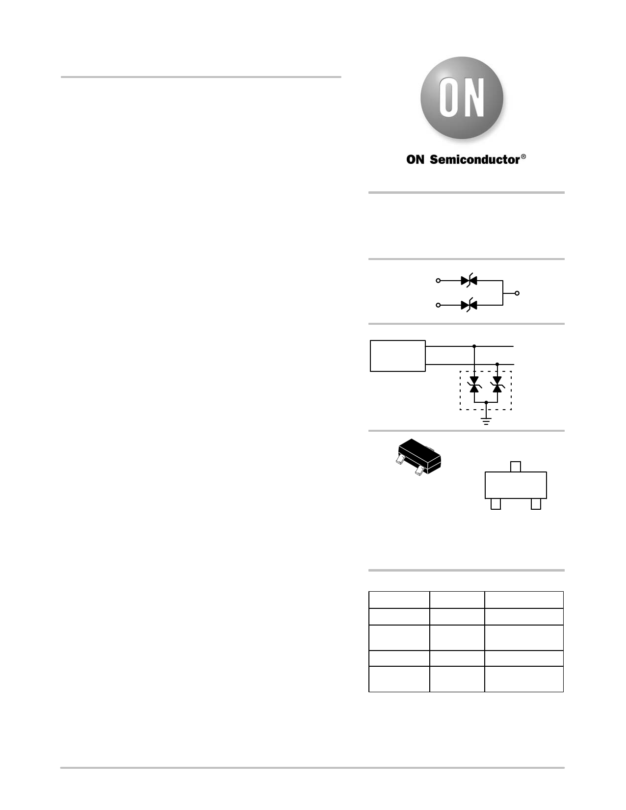
NUP2105L
Dual Line CAN
Bus Protector
The NUP2105L has been designed to protect the CAN transceiver in
high−speed and fault tolerant networks from ESD and other harmful
transient voltage events. This device provides bidirectional protection
for each data line with a single compact SOT−23 package, giving the
system designer a low cost option for improving system reliability and
meeting stringent EMI requirements.
Features
• 350 W Peak Power Dissipation per Line (8 x 20 msec Waveform)
• Low Reverse Leakage Current (< 100 nA)
• Low Capacitance High−Speed CAN Data Rates
• IEC Compatibility: − IEC 61000−4−2 (ESD): Level 4
− IEC 61000−4−4 (EFT): 40 A – 5/50 ns
− IEC 61000−4−5 (Lighting) 8.0 A (8/20 ms)
• ISO 7637−1, Nonrepetitive EMI Surge Pulse 2, 9.5 A
(1 x 50 ms)
• ISO 7637−3, Repetitive Electrical Fast Transient (EFT)
EMI Surge Pulses, 50 A (5 x 50 ns)
• Flammability Rating UL 94 V−0
• Pb−Free Packages are Available
www.DataSheet4U.com
Applications
• Industrial Control Networks
♦ Smart Distribution Systems (SDS™)
♦ DeviceNet™
• Automotive Networks
♦ Low and High−Speed CAN
♦ Fault Tolerant CAN
http://onsemi.com
SOT−23
DUAL BIDIRECTIONAL
VOLTAGE SUPPRESSOR
350 W PEAK POWER
PIN 1
PIN 2
PIN 3
CAN
Transceiver
CAN_H
CAN_L
CAN Bus
NUP2105L
MARKING
DIAGRAM
SOT−23
CASE 318
STYLE 27
27EMG
G
1
27E = Device Code
M = Date Code
G = Pb−Free Package
(Note: Microdot may be in either location)
ORDERING INFORMATION
Device
Package
Shipping†
NUP2105LT1 SOT−23 3000/Tape & Reel
NUP2105LT1G
NUP2105LT3
SOT−23
(Pb−Free)
SOT−23
3000/Tape & Reel
10000/Tape & Reel
NUP2105LT3G SOT−23 10000/Tape & Reel
(Pb−Free)
†For information on tape and reel specifications,
including part orientation and tape sizes, please
refer to our Tape and Reel Packaging Specification
Brochure, BRD8011/D.
© Semiconductor Components Industries, LLC, 2005
July, 2005 − Rev. 4
1
Publication Order Number:
NUP2105L/D
1 page 
NUP2105L
EMI Specifications
The EMI protection level provided by the TVS device can
be measured using the International Organization for
Standardization (ISO) 7637−1 and −3 specifications that are
representative of various noise sources. The ISO 7637−1
specification is used to define the susceptibility to coupled
transient noise on a 12 V power supply, while ISO 7637−3
defines the noise immunity tests for data lines. The ISO 7637
tests also verify the robustness and reliability of a design by
applying the surge voltage for extended durations.
The IEC 61000−4−X specifications can also be used to
quantify the EMI immunity level of a CAN system. The IEC
61000−4 and ISO 7637 tests are similar; however, the IEC
standard was created as a generic test for any electronic
system, while the ISO 7637 standard was designed for
vehicular applications. The IEC61000−4−4 Electrical Fast
Transient (EFT) specification is similar to the ISO 7637−1
pulse 1 and 2 tests and is a requirement of SDS CAN
systems. The IEC 61000−4−5 test is used to define the power
absorption capacity of a TVS device and long duration
voltage transients such as lightning. Table 2 provides a
summary of the ISO 7637 and IEC 61000−4−X test
specifications. Table 3 provides the NUP2105L’s ESD
test results.
Table 2. ISO 7637 and IEC 61000−4−X Test Specifications
Test
Waveform
Test Specifications
NUP2105L Test
Simulated Noise Source
ISO 7637−1
Pulse 1
Vs = 0 to −100 V
Imax = 10 A
tduration = 5000 pulses
Imax = 1.75 A
Vclamp_max = 31 V
tduration = 5000 pulses
Ri = 10 W, tr = 1.0 ms,
td_10% = 2000 ms, t1 = 2.5 s,
t2 = 200 ms, t3 = 100 ms
DUT in parallel with
inductive load that is
disconnected from power
supply.
12 V Power Supply Lines
Pulse 2
Vs = 0 to +100 V
Imax = 10 A
tduration = 5000 pulses
Imax = 9.5 A
Vclamp_max = 33 V
tduration = 5000 pulses
Ri = 10 W, tr = 1.0 ms,
td_10% = 50 ms, t1 = 2.5 s,
t2 = 200 ms
DUT in series with inductor
that is disconnected.
ISO 7637−3
Data Line EFT
Pulse ‘a’
Pulse ‘b’
Vs = −60 V
Imax = 1.2 A
tduration = 10 minutes
Vs = +40 V
Imax = 0.8 A
Imax = 50 A
Vclamp_max = 40 V
tduration = 60 minutes
Ri = 50 W, tr = 5.0 ns,
td_10% = 0.1 ms, t1 = 100 ms,
t2 = 10 ms, t3 = 90 ms
Switching noise of inductive
loads.
tduration = 10 minutes
IEC 61000−4−4
Vopen circuit = 2.0 kV
Ishort circuit = 40 A
(Level 4 = Severe Industrial
Environment)
(Note 2)
Switching noise of inductive
loads.
Data Line EFT
Ri = 50 W, tr < 5.0 ns,
td_50% = 50 ns, tburst = 15 ms,
fburst = 2.0 to 5.0 kHz,
trepeat = 300 ms
tduration = 1 minute
IEC 61000−4−5
Vopen circuit = 1.2 x 50 ms,
Ishort circuit = 8 x 20 ms
Ri = 50 W
Lightning, nonrepetitive
power line and load
switching
1. DUT = device under test.
2. The EFT immunity level was measured with test limits beyond the IEC 61000−4−4 test, but with the more severe test conditions of
ISO 7637−3.
Table 3. NUP2105L ESD Test Results
ESD Specification
Test
Human Body Model
Contact
IEC 61000−4−2
Contact
Non−contact (Air Discharge)
3. Test equipment maximum test voltage is 30 kV.
Test Level
16 kV
30 kV (Note 3)
30 kV (Note 3)
Pass
Pass
Pass
Pass / Fail
http://onsemi.com
5
5 Page | ||
| Páginas | Total 8 Páginas | |
| PDF Descargar | [ Datasheet NUP2105L.PDF ] | |
Hoja de datos destacado
| Número de pieza | Descripción | Fabricantes |
| NUP2105L | Dual Line CAN Bus Protector | ON Semiconductor |
| Número de pieza | Descripción | Fabricantes |
| SLA6805M | High Voltage 3 phase Motor Driver IC. |
Sanken |
| SDC1742 | 12- and 14-Bit Hybrid Synchro / Resolver-to-Digital Converters. |
Analog Devices |
|
DataSheet.es es una pagina web que funciona como un repositorio de manuales o hoja de datos de muchos de los productos más populares, |
| DataSheet.es | 2020 | Privacy Policy | Contacto | Buscar |