|
|
|
PDF RE46C129 Data sheet ( Hoja de datos )
| Número de pieza | RE46C129 | |
| Descripción | CMOS Ionization Smoke Detector ASIC | |
| Fabricantes | R & E International | |
| Logotipo | ||
Hay una vista previa y un enlace de descarga de RE46C129 (archivo pdf) en la parte inferior de esta página. Total 8 Páginas | ||
|
No Preview Available !
www.DataSheet4U.com
R&E International
RE46C129
CMOS Ionization Smoke Detector ASIC with Interconnect
Product Specification
General Description
The RE46C129 is low power CMOS ionization type
smoke detector IC. With few external components this
circuit will provide all the required features for an
ionization type smoke detector.
An internal oscillator strobes power to the smoke
detection circuitry for 10.5mS every 1.66 seconds to
keep standby current to a minimum. A check for a low
battery condition is performed every 40 seconds when
in standby.
An interconnect pin allows multiple detectors to be
connected such that when one units alarms all units will
sound.
Although this device was designed for smoke detection
utilizing an ionization chamber it could be used in a
variety of security applications.
Utilizing low power CMOS technology the RE46C129
was designed for use in smoke detectors that comply
with Underwriters Laboratory Specification UL217 and
UL268.
Features
• Guard Outputs for Ion Detector Input
• +/-0.75pA Detect Input Current
• Internal Reverse Battery Protection
• Low Quiescent Current Consumption (<6.5uA)
• Available in 16L PDIP or 16L N SOIC
• ESD Protection on all Pins
• Internal Low Battery Detection
• Interconnect up to 40 Detectors
• Compatible with Allegro A5350
• Available in Standard Packaging or RoHS Compliant
Pb Free Packaging.
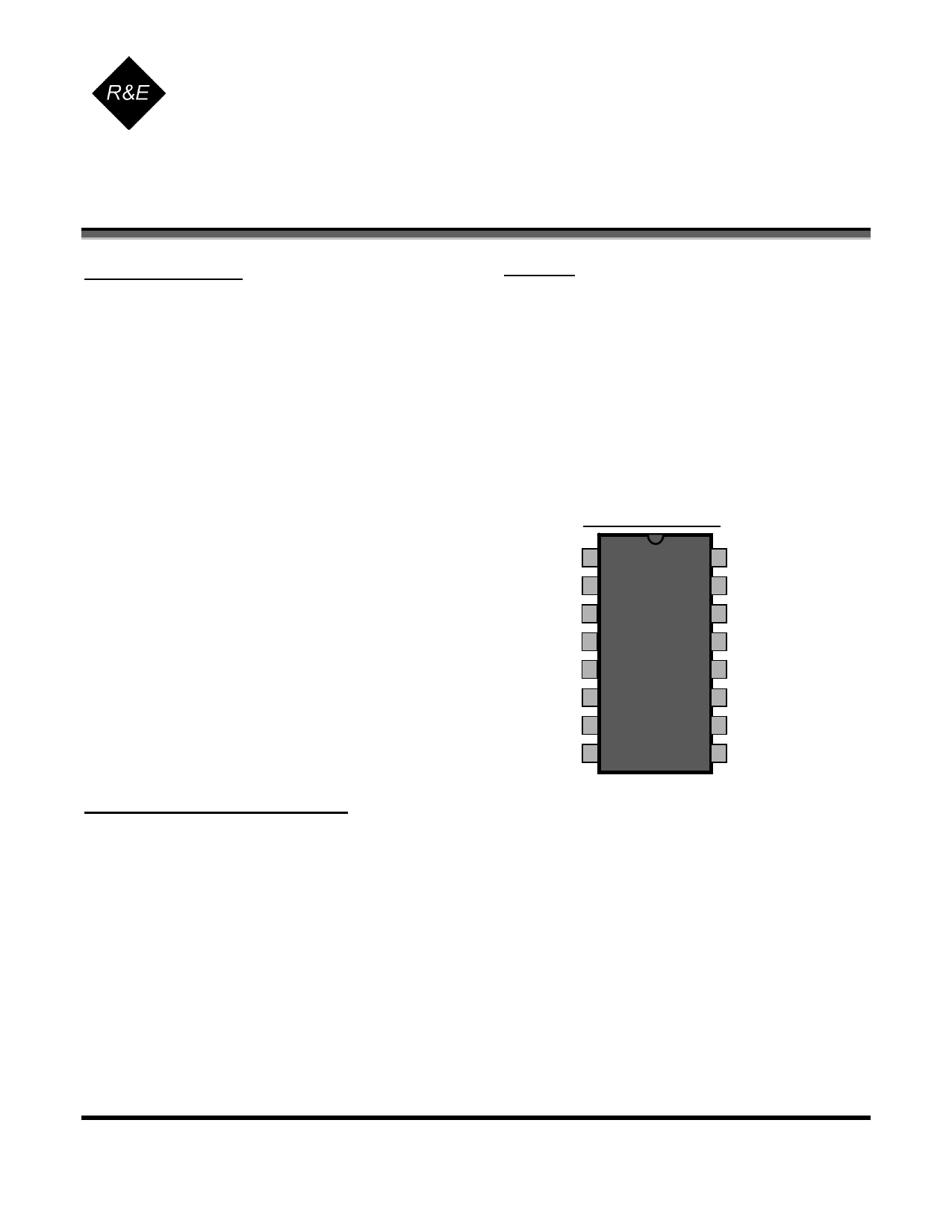
Pin Configuration
NC
IO
LBADJ
NC
LED
VDD
RBIAS
FEED
1
2
3
4
5
6
7
8
16 GUARD2
15 DETECT
14 GUARD1
13 VSEN
12 OSCAP
11 HS
10 HB
9 VSS
ABSOLUTE MAXIMUM RATINGS
PARAMETER
Supply Voltage
Input Voltage Range Except FEED, IO
FEED Input Voltage Range
IO Input Voltage Range
Reverse Battery Time
Input Current except FEED
Operating Temperature
Storage Temperature
Maximum Junction Temperature
SYMBOL
VDD
Vin
Vinfd
Vio1
TRB
Iin
TA
TSTG
TJ
VALUE
15
-.3 to Vdd +.3
-10 to +22
-.3 to 17
5
10
-10 to 60
-55 to 125
150
UNITS
V
V
V
V
S
mA
°C
°C
°C
Stresses beyond those listed under Absolute Maximum Ratings may cause permanent damage to the device. These are
stress ratings only and operation at these conditions for extended periods may affect device reliability.
This product utilizes CMOS technology with static protection; however proper ESD prevention procedures should be used
when handling this product. Damage can occur when exposed to extremely high static electrical charge.
Telephone 610.992.0727
Facsimile 610.992.0734
E-mail: [email protected]
Page 1 of 8
DS-RE46C129-121806
This datasheet contains PROPRIETARY and CONFIDENTIAL information.
1 page 
RE46C129
CMOS Ionization Smoke Detector ASIC with Interconnect
Product Specification
R&E International
DEVICE DESCRIPTION and APPLICATION NOTES
Internal Timing – With external components as indicated on the application drawing the period of the
oscillator is nominally 1.67 seconds in standby. Every 1.66 seconds the detection circuitry is powered up
for 10.5mS and the status of the smoke comparator is latched. In addition every 40 seconds the LED
driver is turned on for 10.5mS and the status of the low battery comparator is latched. The smoke
comparator status is not checked during the low battery test, during the low battery horn warning chirp, or
when the horn is on due to an alarm condition.
If an alarm condition is detected the oscillator period increases to 41.5mS. In any alarm condition the
horn is on for 166mS and off for 83mS (typical).
Due to the low currents used in the oscillator the capacitor on pin 12 should be a low leakage type.
Oscillator accuracy will depend mainly on the tolerance of the RBIAS resistor and OSCAP capacitor.
Smoke Detection Circuit – The smoke comparator compares the ionization chamber voltage to a voltage
derived from a resistor divider across VDD. This divider voltage must be provided externally on pin 13
(VSEN). See the application drawing (FIG 2).
The guard amplifier and outputs are always active and will be within 50mV of the DETECT input to
reduce surface leakage. The guard outputs also allow for measurement of the DETECT input without
loading the ionization chamber.
Low Battery Detection - An internal reference is compared to the voltage divided VDD supply. The
battery can be checked under load via the LED low side driver output since low battery status is latched
at the end of the 10.5mS LED pulse. Pin 3 (LBADJ) can be used to modify the low battery set point by
placing a resistor to VDD or VSS. The transmission switch on LBADJ is turned on during the LED pulse
so an external resistance can be added on pin 3 to modify the set point if desired.
LED Pulse – The LED is pulsed on for 10.5mS every 40S in standby. In alarm the LED is pulsed on for
10.5mS every 1S.
Interconnect – Pin 2 (IO) provides the capability to common many detectors in a single system. If a single
unit goes into alarm the IO pin is driven high. This high signal causes the interconnected units to alarm.
The LED flashes every 1S for 10.5mS on the signaling unit and is inhibited on the units that are in alarm
due to the active IO signal. An internal sink device on the IO pin helps to discharge the interconnect line.
This charge dump device is active for 1 clock cycle after the unit exits a local alarm condition (1.67S).
The interconnect input has a 500mS nominal digital filter which will filter out pulsed signals on the IO pin.
This allows for interconnection to other types of alarms (carbon monoxide for example) that may have a
pulsed interconnect signal. This filter will eliminate unwanted random horn activations caused by a pulsed
(<500ms nominal) IO input signal.
Testing - By holding pin 12 (OSCAP) low the internal power strobe is active. Functional testing can be
accelerated by driving pin 12 with a 4kHZ square wave however the 10.5mS strobe period must be
maintained for proper operation of the analog circuitry. Please refer to the timing diagrams. All internal
timing is reset after a power up. By holding pins 8 and 12 low, reducing VDD and monitoring Pin 10 the
low battery trip level can be measured at power up.
Telephone 610.992.0727
Facsimile 610.992.0734
E-mail: [email protected]
Page 5 of 8
DS-RE46C129-121806
This datasheet contains PROPRIETARY and CONFIDENTIAL information.
5 Page | ||
| Páginas | Total 8 Páginas | |
| PDF Descargar | [ Datasheet RE46C129.PDF ] | |
Hoja de datos destacado
| Número de pieza | Descripción | Fabricantes |
| RE46C120 | CMOS Ionization Smoke Detector ASIC | R & E International |
| RE46C121 | CMOS Ionization Smoke Detector ASIC | R & E International |
| RE46C122 | CMOS Ionization Smoke Detector ASIC | Microchip |
| RE46C126 | CMOS Ionization Smoke Detector ASIC | R & E International |
| Número de pieza | Descripción | Fabricantes |
| SLA6805M | High Voltage 3 phase Motor Driver IC. |
Sanken |
| SDC1742 | 12- and 14-Bit Hybrid Synchro / Resolver-to-Digital Converters. |
Analog Devices |
|
DataSheet.es es una pagina web que funciona como un repositorio de manuales o hoja de datos de muchos de los productos más populares, |
| DataSheet.es | 2020 | Privacy Policy | Contacto | Buscar |