|
|
|
PDF IP2003 Data sheet ( Hoja de datos )
| Número de pieza | IP2003 | |
| Descripción | MULTIPHASE OPTIMIZED LGA POWER BLOCK | |
| Fabricantes | International Rectifier | |
| Logotipo | ||
Hay una vista previa y un enlace de descarga de IP2003 (archivo pdf) en la parte inferior de esta página. Total 9 Páginas | ||
|
No Preview Available !
www.DataSheet4U.com
PD- 96922A
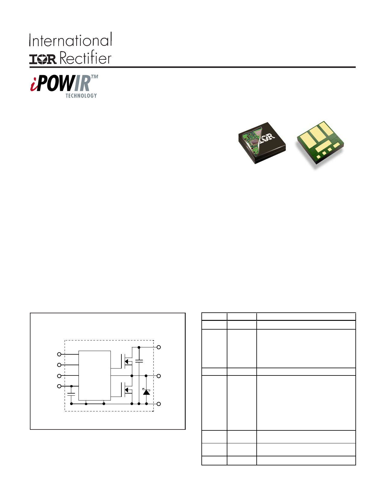
iP2003
Synchronous Buck
Multiphase Optimized LGA Power Block
Features:
Integrated Power Semiconductors, Drivers & Passives
Full function multiphase building block
Output current 40A continuous with no derating up to
TPCB = 100°C and TCASE = 100°C
Operating frequency up to 1.0 MHz
Efficient dual sided cooling
Small footprint low profile (11mm x 11mm x 2.2mm) package
Optimized for very low power losses
LGA interface
Ease of design
Proprietary packaging enables ultra low Rthj-case top
Description
iP2003 Power Block
The iP2003 is a fully optimized solution for high current synchronous buck multiphase applications.
Board space and design time are greatly reduced because most of the components required for each
phase of a typical discrete-based multiphase circuit are integrated into a single 11mm x 11mm x 2.2mm
power block. The only additional components required for a complete multiphase converter are a PWM IC, the
external inductors, and the input and output capacitors.
iPOWIR technology offers designers an innovative board space saving solution for applications
requiring high power densities. iPOWIR technology eases design for applications where component integration
offers benefits in performance and functionality. iPOWIR technology solutions are also optimized internally for
layout, heat transfer and component selection.
iP2003 Internal Block Diagram
P RDY
ENABLE
PWM
VDD
SGND
MOSFET
Driver with
dead time
cont ro l
www.irf.com
VIN
VSW
P GND
Pin #
1
2
3
4
5, 7
11/18/04
6
8
Pin Name Pin Function
VDD Supply voltage for the internal circuitry.
When set to logic level high, internal circuitry
of the device is enabled. When set to logic
ENABLE level low, the PRDY pin is forced low, the
Control and Sychronous switches are turned
off, and the supply current is less than 10µA.
PWM TTL-level input signal to MOSFET drivers.
PRDY
Power Ready - This pin indicates the status of
ENABLE or VDD. This output will be driven
low when ENABLE is logic low or when VDD
is less than 4.4V (typ.). When ENABLE is
logic high and VDD is greater than 4.4V (typ.),
this output is driven high. This output has a
10mA source and 1mA sink capability.
PGND
VSW
VIN
Power Ground - connection to the ground of
bulk and filter capacitors.
Switching Node - connection to the output
inductor.
Input voltage for the DC-DC converter.
1
1 page 
iP2003
Applying the Safe Operating Area (SOA) Curve
The SOA graph incorporates power loss and thermal resistance information in a way that allows one to solve for maximum
current capability in a simplified graphical manner. It incorporates the ability to solve thermal problems where heat is drawn
out through the printed circuit board and the top of the case.
Case Temperature (ºC)
Procedure
0 10 20 30 40 50 60 70 80 90 100 110 120
42
40
1) Draw a line from Case Temp axis at TCASE to the PCB
Temp axis at TPCB.
38
36
34
32
30
2) Draw a vertical line from the TX axis intercept to the SOA
curve.
3) Draw a horizontal line from the intersection of the vertical
line with the SOA curve to the Y-axis. The point at which
the horizontal line meets the Y-axis is the SOA current.
28
26
24
22
20
18
16
14
12
10
8
6
4
VIN = 12V
VOUT = 1.3V
fSW = 1MHz
L=0.3uH
Safe
Operating
Area
TX
2
0
0 10 20 30 40 50 60 70 80 90 100 110 120
PCB Temperature (ºC)
Calculating Power Loss and SOA for Different Operating Conditions
To calculate power loss for a given set of operating conditions, the following procedure should be followed:
Determine the maximum current for each iP2003 and obtain the maximum power loss from Fig 1. Use the curves in
Figs. 3, 4, 5 and 6 to obtain normalized power loss values that match the operating conditions in the application. The
maximum power loss under the operating conditions is then the product of the power loss from Fig. 1 and the normal-
ized values.
To calculate the SOA for a given set of operating conditions, the following procedure should be followed:
Determine the maximum PCB temperature and Case temperature at the maximum operating current of each iP2003.
Obtain the SOA temperature adjustments that match the operating conditions in the application from Figs. 3, 4, 5 and
6. Then, add the sum of the SOA temperature adjustments to the Tx axis intercept in Fig 2.
The example below explains how to calculate maximum power loss and SOA.
Example:
Operating Conditions
Output Current = 40A
Sw Freq= 900kHz
Calculating Maximum Power Loss:
Input Voltage = 10V
Inductor = 0.2µH
Output Voltage = 3.3V
TPCB = 100°C, TCASE = 110°C
(Fig. 1)
(Fig. 3)
(Fig. 4)
(Fig. 5)
(Fig. 6)
Maximum power loss = 15W
Normalized power loss for input voltage ≈ 0.98
Normalized power loss for output voltage ≈ 1.14
Normalized power loss for frequency ≈ 0.94
Normalized power loss for inductor value ≈ 1.013
Calculated Maximum Power Loss for given conditions = 15W x 0.98 x 1.14 x 0.94 x 1.013 ≈ 15.96W
www.irf.com
5
5 Page | ||
| Páginas | Total 9 Páginas | |
| PDF Descargar | [ Datasheet IP2003.PDF ] | |
Hoja de datos destacado
| Número de pieza | Descripción | Fabricantes |
| IP2002 | Synchronous Buck Synchronous Buck Integrated Power Semiconductors/ Drivers & Passives | International Rectifier |
| IP2003 | MULTIPHASE OPTIMIZED LGA POWER BLOCK | International Rectifier |
| IP2003A | Synchronous Buck Multiphase Optimized LGA Power Block Integrated Power Semiconductors | International Rectifier |
| IP2003APBF | Synchronous Buck Multiphase Optimized LGA Power Block Intergrated Power Semiconductors | International Rectifier |
| Número de pieza | Descripción | Fabricantes |
| SLA6805M | High Voltage 3 phase Motor Driver IC. |
Sanken |
| SDC1742 | 12- and 14-Bit Hybrid Synchro / Resolver-to-Digital Converters. |
Analog Devices |
|
DataSheet.es es una pagina web que funciona como un repositorio de manuales o hoja de datos de muchos de los productos más populares, |
| DataSheet.es | 2020 | Privacy Policy | Contacto | Buscar |