|
|
|
PDF CE-3101 Data sheet ( Hoja de datos )
| Número de pieza | CE-3101 | |
| Descripción | DC-DC Converter | |
| Fabricantes | TDK Electronics | |
| Logotipo | ||
Hay una vista previa y un enlace de descarga de CE-3101 (archivo pdf) en la parte inferior de esta página. Total 2 Páginas | ||
|
No Preview Available !
www.DataSheet4U.com
Non-insulation, 8-pin SMD type, 1.2W output
CE-3101
A321_CE_3101
(1/2)
TDK DC-DC Converter
SPECIFICATIONS AND STANDARDS
PART NO.
CE-3101
Maximum output power W
1.2
INPUT CONDITIONS
Input voltage Edc
V +4.5 to +5.5(5V typ.)
Efficiency(typ.)∗1
% 72
OUTPUT CHARACTERISTICS
Output voltage Edc
V
+40
Maximum output current mA
30
Output voltage setting deviation(max.) %
±4
Input variation(max.)
%
±1
Load variation(max.)
%
±1
Temperature variation(max.) %
±1.5
Ripple noise Ep-p(typ.)∗1, ∗2 mV
250
∗1 Typical input voltage, maximum output current, ambient temperature
25°C.
∗2 Measuring frequency: 20MHz
Output ripple noise is measured after connection of the indicated
external capacitor Co to the output terminals.
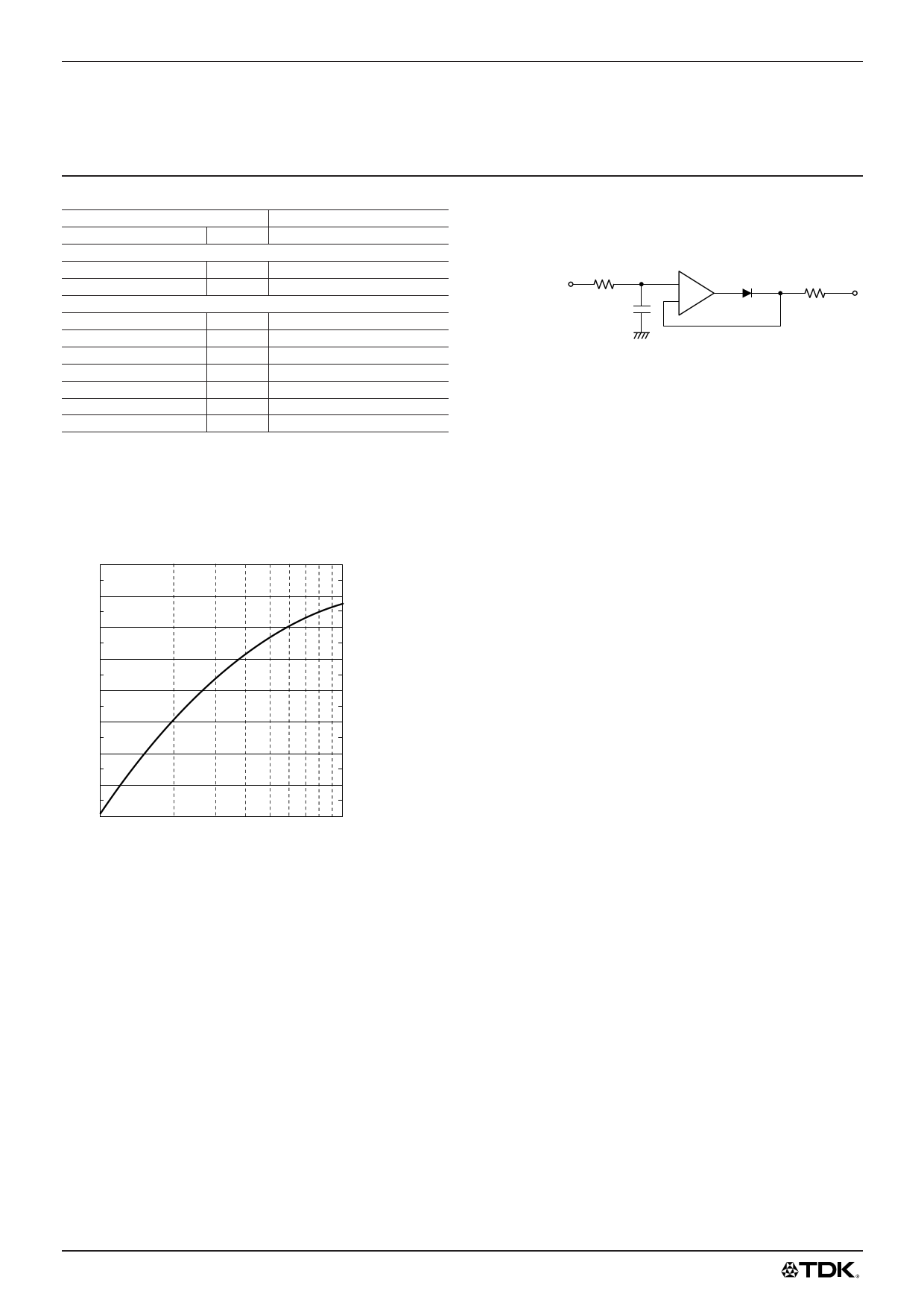
OUTPUT VOLTAGE VARIABLE CHARACTERISTICS
40
38
36
34
32
30
28
26
24
100
200 300 400 500
RA(kΩ)
1000
PACKAGING STYLE AND QUANTITY
• Tray(1 layer: 50 pieces, 1 carton: 450 pieces max.)
• Taping(500 pieces)
OUTPUT VOLTAGE CONTROL
[EXTERNAL APPLIED VOLTAGE METHOD]
An external voltage is applied by the external circuit below. This
controls the output voltage(Vout).
R1
External voltage
+ D1 R2
Vs
C1 –
Vout=[0.5769–(External voltage–0.75)/R2]×68+0.75
Voltage: V
Resistance: kΩ
R1, C1: For removal of line noise
D1: Fast recovery diode
The external voltage range should be determined by the
following expression:
External voltage<R2×1mA+2.5(Unit: V)
[EXTERNAL RESISTANCE METHOD]: Refer to OUTPUT
VOLTAGE VARIABLE CHARACTERISTICS
An external resistance RA is placed between terminal No.
5(Vout) and No.6(Vset). This controls the output voltage(Vout).
Voltage changes per the following equation.
Vout=0.5769×[68×RA/(69.3+RA)]+0.75
Voltage: V
Resistance: kΩ
Recommended resistance range is 100 to 1000 kΩ.
RECOMMENDED SOLDERING CONDITIONS
Method: Infrared(or hot air) reflow method
Reflow temperature and time : 230°C max., 5s min.
: over 200°C, 40s min.
Preheating temperature and time: 130 to 160°C, 90s min.
Reflow cycle: 1 time(Vibrations should be avoided during reflow.)
PRECAUTIONS
• Install the components according to CIRCUIT DIAGRAM.
• This product operates only after the input-capacitor is
connected.
• Parallel operation to increase output current is not possible.
• Input fuse
A fuse should be connected to the input with a current rating 3
times that of the rated(normal) input current.
All specifications are subject to change without notice.
1 page | ||
| Páginas | Total 2 Páginas | |
| PDF Descargar | [ Datasheet CE-3101.PDF ] | |
Hoja de datos destacado
| Número de pieza | Descripción | Fabricantes |
| CE-3101 | DC-DC Converter | TDK Electronics |
| Número de pieza | Descripción | Fabricantes |
| SLA6805M | High Voltage 3 phase Motor Driver IC. |
Sanken |
| SDC1742 | 12- and 14-Bit Hybrid Synchro / Resolver-to-Digital Converters. |
Analog Devices |
|
DataSheet.es es una pagina web que funciona como un repositorio de manuales o hoja de datos de muchos de los productos más populares, |
| DataSheet.es | 2020 | Privacy Policy | Contacto | Buscar |