|
|
|
PDF AD1937 Data sheet ( Hoja de datos )
| Número de pieza | AD1937 | |
| Descripción | (AD1935 - AD1939) 4 ADC/8 DAC | |
| Fabricantes | Analog Devices | |
| Logotipo | ||
Hay una vista previa y un enlace de descarga de AD1937 (archivo pdf) en la parte inferior de esta página. Total 30 Páginas | ||
|
No Preview Available !
www.DataSheet4U.com
Preliminary Technical Data
4 ADC/8 DAC with PLL,
192 kHz, 24 Bit CODEC
AD1935/AD1936/AD1937/AD1938/AD1939
Features
PLL generated (32-192kHz) or direct master clock
Low EMI design
109 dB DAC/ 107dB ADC Dynamic Range and SNR
-94dB THD+N
Single 3.3V Supply
Tolerance for 5V logic inputs
Supports 24-bits and 8 kHz - 192 kHz sample rates
Differential ADC input
Single-ended or Differential DAC output versions
Log volume control with "auto-ramp" function
Hardware and software controllable clickless mute
Software and hardware power-down
Right justified, left justified, I2S and TDM Modes
Master and slave modes up to 16 channel in/out
48-lead LQFP or 64-lead LQFP plastic package
Applications
Automotive audio systems
Home theater systems
Set-top boxes
Digital audio effects processors
GENERAL DESCRIPTION
The AD193X family are high performance, single-chip codecs that
provide 4 ADCs with differential input and 8 DACs with either
single-ended or differential output using ADI’s patented multibit
sigma-delta architecture. An SPI® or I2C® port is included, allowing
a microcontroller to adjust volume and many other parameters.
The AD193X family operates from 3.3V digital and analog supplies.
The AD193X is available in a 48-lead (SE output) or 64-lead
(differential output) LQFP package.
The AD193X is designed for low EMI. This consideration is
apparent in both the system and circuit design architectures. By
using the on-board PLL to derive master clock from L-R clock, the
AD193X eliminates the need for a separate high frequency master
clock. It can also be used with a suppressed bit clock. The D-A and
A-D converters are designed using the latest ADI continuous time
architectures to further minimize EMI. By using 3.3V supplies,
power consumption is minimized, further reducing emissions.
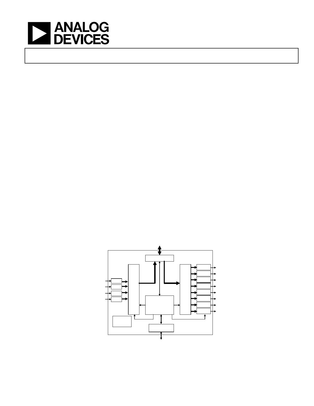
Functional Block Diagram
Digital Audio
Input/Output
Analog
Audio
Inputs
AD193X
Serial Data Port
ADC
SDATAOUT
SDATAIN Digital
Digital
Filter
ADC Filter
&
ADC
CLOCKS
Volume
Control
ADC Timing Management
&
Control
(Clock & PLL)
Precision
Voltage
Reference
Control Port
SPI / I2C
DAC
DAC
DAC
DAC
DAC
DAC
DAC
DAC
Analog
Audio
Outputs
Control Data
Input/Output
Figure 1
Rev. PrI
Information furnished by Analog Devices is believed to be accurate and reliable.
However, no responsibility is assumed by Analog Devices for its use, nor for any
infringements of patents or other rights of third parties that may result from its use.
Specifications subject to change without notice. No license is granted by implication
or otherwise under any patent or patent rights of Analog Devices. Trademarks and
registered trademarks are the property of their respective companies.
One Technology Way, P.O. Box 9106, Norwood, MA 02062-9106, U.S.A.
Tel: 781.329.4700
www.analog.com
Fax: 781.326.8703 © 2005 Analog Devices, Inc. All rights reserved.
1 page 
Preliminary Technical Data
Parameter
I2C PORT
Start Condition
Stop Condition
Slave Mode
DAC SERIAL PORT
Master Mode
Slave Mode
ADC SERIAL PORT
Master Mode
AUXILIARY INTERFACE
fCCLK
tCDS
tCDH
tCLS
tCLH
tCLH
tCOE
tCOD
tCOH
tCOTS
fSCL
tSCLH
tSCLL
tSCS
tSCH
tDS
tSCR
tSCF
tSDR
tSDF
tSCS
tDBH
tDBL
fDB
tDLS
tDLH
tDLS
tDDS
tDDH
tABH
tABL
fDB
tALS
tALH
tALS
tABDD
tAXDS
tAXDH
tDXDD
tXBH
tXBL
fXB
tDLS
tDLH
AD1935/AD1936/AD1937/AD1938/AD1939
Comments
CCLK Frequency
CDATA Setup
To CCLK Rising
CDATA Hold
From CCLK Rising
CLATCH Setup
To CCLK Rising
CLATCH Hold
From CCLK Falling
CLATCH High
COUT Enable
From CCLK Falling
COUT Delay
COUT Hold
From CCLK Falling
From CCLK Falling
COUT Three-State
SCL Clock
Frequency
From CCLK Falling
SCL High
SCL Low
Setup Time
Relevant for Repeated Start
Condition
Hold Time
After this period the 1st clock is
generated
Data Setup Time
SCL Rise Time
SCL Fall Time
SDA Rise Time
SDA Fall Time
Setup Time
DBCLK High
DBCLK Low
DBCLK Frequency
DLRCLK Setup
To DBCLK Rising
DLRCLK Hold
DLRCLK Skew
From DBCLK Rising
From DBCLK Falling
DSDATA Setup
To DBCLK Rising
DSDATA Hold
From DBCLK Rising
ABCLK High
ABCLK Low
ABCLK Frequency
ALRCLK Setup
To ABCLK Rising
ALRCLK Hold
From ABCLK Rising
ALRCLK Skew
From ABCLK Falling
ASDATA Delay
From ABCLK Falling
AAUXDATA Setup To AUXBCLK Rising
AAUXDATA Hold From AUXBCLK Rising
DAUXDATA Delay From AUXBCLK Falling
AUXBCLK High
AUXBCLK Low
AUXBCLK
Frequency
AUXLRCLK Setup
To AUXBCLK Rising
AUXLRCLK Hold
From AUXBCLK Rising
Table 8
Min Max
20
TBD
TBD
TBD
TBD
TBD
TBD
TBD
TBD
TBD
400
0.6
1.3
0.6
0.6
100
300
300
300
300
0.6
TBD
TBD
TBD
TBD
TBD
TBD TBD
TBD
TBD
TBD
TBD
TBD
TBD
TBD
TBD TBD
TBD
TBD
TBD
TBD
TBD
TBD
TBD
TBD
TBD
Unit
MHz
ns
ns
ns
ns
ns
ns
ns
ns
ns
kHz
µS
µS
µS
µS
ns
ns
ns
ns
ns
µS
ns
ns
ns
ns
ns
ns
ns
ns
ns
ns
ns
ns
ns
ns
ns
ns
ns
ns
ns
ns
ns
ns
ns
Rev. PrI | Page 5 of 30
5 Page 
Preliminary Technical Data
AD1935/AD1936/AD1937/AD1938/AD1939
SCK
SDA
START BY
MASTER
0
0 0 0 1 AD1 AD0 R/W
0
FRAME 1
CHIP ADDRESS BYTE
ACK. BY
AD193X
00 00 11
FRAME 2
REGISTER ADDRESS BYTE
0
ACK. BY
AD193X
SCK
(CONTINUED)
SDA
(CONTINUED)
D7 D6 D5 D4 D3 D2 D1 D0
FRAME 3
DATA BYTE TO
AD193X
ACK. BY STOP BY
AD193X MASTER
Figure 11. Format of I2C Write
SCL
SDA
START BY
MASTER
0
SCL
(Continued)
SDA
(Continued)
0
REPEATED START
BY MASTER
0 0 0 1 AD1 AD0 R/W
0
FRAME 1
CHIP ADDRESS BYTE
ACK. BY
AD193X
00 00 11
FRAME 2
REGISTER ADDRESS BYTE
0
ACK. BY
AD193X
0 0 0 1 AD1 AD0 R/W
D7 D6 D5 D4 D3 D2 D1 D0
FRAME 3
CHIP ADDRESS BYTE
ACK. BY
AD193X
FRAME 4
REGISTER DATA
ACK. BY STOP BY
AD193X MASTER
Figure 12. Format of I2C Read
Power Supply and Voltage Reference
outputs are driven from the 3.3 V DVDD supply and are
compatible with TTL and 3.3 V CMOS levels.
The AD193X is designed for 3.3 V supplies. Separate power supply
pins are provided for the analog and digital sections. These pins
should be bypassed with 100 nF ceramic chip capacitors, as close to
the pins as possible, to minimize noise pickup. A bulk aluminum
electrolytic capacitor of at least 22 µF should also be provided on
the same PC board as the codec. For critical applications, improved
performance will be obtained with separate supplies for the analog
and digital sections. If this is not possible, it is recommended that
the analog and digital supplies be isolated by means of a ferrite
bead in series with each supply. It is important that the analog
supply be as clean as possible.
The AD1935 (64-pin single-ended version), and the AD1939 and
AD1937 (64-pin differential versions) include a 3.3V regulator
driver which requires only an external pass transistor and bypass
capacitors to make a 5V to 3.3V regulator. If the regulator driver is
not used, VSUPPLY, VDRIVE, and VSENSE should be connected to
DGND.
All digital inputs are compatible with TTL and CMOS levels. All
The ADC and DAC internal voltage reference VREF is brought out
on FILTR and should be bypassed as close as possible to the chip,
with a parallel combination of 10 µF and 100 nF. Any external
current drawn should be limited to less than 50 µA.
The internal reference can be disabled in PLL and Clock Control
Register 1 and FILTR driven from an external source. This can be
used to scale the DAC output to a power amplifier's clipping level
based on its power supply voltage. The ADC input gain will also
vary by the inverse ratio. The total gain from ADC input to DAC
output will stay constant.
The CM pin is the internal common-mode reference. It should be
bypassed as close as possible to the chip, with a parallel
combination of 10 µF and 100 nF. This voltage may be used to bias
external op amps to the common-mode voltage of the input and
output signal pins. The output current should be limited to less
than 0.5 mA source and 2 mA sink.
Rev. PrI | Page 11 of 30
11 Page | ||
| Páginas | Total 30 Páginas | |
| PDF Descargar | [ Datasheet AD1937.PDF ] | |
Hoja de datos destacado
| Número de pieza | Descripción | Fabricantes |
| AD1933 | 8 DAC | Analog Devices |
| AD1934 | 8-Channel DAC | Analog Devices |
| AD1935 | (AD1935 - AD1939) 4 ADC/8 DAC | Analog Devices |
| AD1936 | (AD1935 - AD1939) 4 ADC/8 DAC | Analog Devices |
| Número de pieza | Descripción | Fabricantes |
| SLA6805M | High Voltage 3 phase Motor Driver IC. |
Sanken |
| SDC1742 | 12- and 14-Bit Hybrid Synchro / Resolver-to-Digital Converters. |
Analog Devices |
|
DataSheet.es es una pagina web que funciona como un repositorio de manuales o hoja de datos de muchos de los productos más populares, |
| DataSheet.es | 2020 | Privacy Policy | Contacto | Buscar |