|
|
|
PDF MAAPGM0041 Data sheet ( Hoja de datos )
| Número de pieza | MAAPGM0041 | |
| Descripción | Power Amplifier | |
| Fabricantes | Tyco Electronics | |
| Logotipo | ||
Hay una vista previa y un enlace de descarga de MAAPGM0041 (archivo pdf) en la parte inferior de esta página. Total 5 Páginas | ||
|
No Preview Available !
www.DataSheet4U.com
Amplifier, Power, 1.3W
11.5—15.0 GHz
Features
♦ 1.3 Watt Saturated Output Power Level
♦ Variable Drain Voltage (4-10V) Operation
♦ MSAG™ Process
♦ High Performance Ceramic Bolt Down Package
Primary Applications
♦ Point-to-Point Radio
♦ SatCom
♦ Radio Location
Description
The MAAPGM0041 is a packaged, 3-stage, 1.3 W power amplifier
with on-chip bias networks in a bolt down ceramic package,
allowing easy assembly. This product is fully matched to 50 ohms
on both the input and output. It can be used as a power amplifier
stage or as a driver stage in high power applications.
Fabricated using M/A-COM’s repeatable, high performance and
highly reliable GaAs Multifunction Self-Aligned Gate (MSAG™)
Process, each device is 100% RF tested on wafer to ensure
performance compliance.
M/A-COM’s MSAG™ process features robust silicon-like
manufacturing processes, planar processing of ion implanted
transistors, multiple implant capability enabling power, low-noise,
switch and digital FETs on a single chip, and polyimide scratch
protection for ease of use with automated manufacturing
processes. The use of refractory metals and the absence of
platinum in the gate metal formulation prevents hydrogen
poisoning when employed in hermetic packaging.
Maximum Operating Conditions 1
MAAPGM0041
903208 —
Preliminary Information
APGM0041
YWWXXX
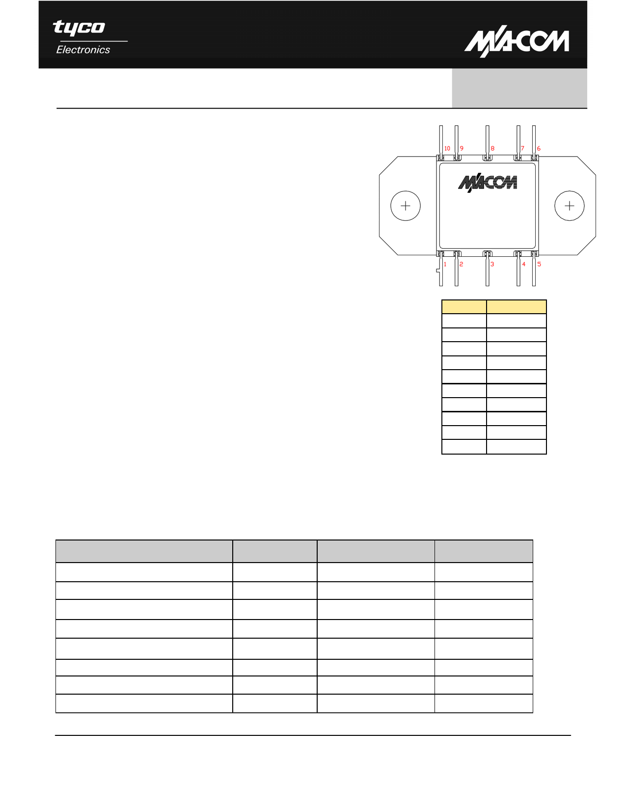
Pin Number
1
2
3
4
5
6
7
8
9
10
Description
No Connection
No Connection
RF IN
No Connection
VGG
No Connection
No Connection
RF OUT
No Connection
VDD
Parameter
Symbol
Absolute Maximum
Units
Input Power
Drain Supply Voltage
Gate Supply Voltage
Quiescent Drain Current (No RF, 40% Idss)
Quiescent DC Power Dissipated (No RF)
PIN
VDD
VGG
IDQ
PDISS
21.0
+12.0
-3.0
810
6.5
dBm
V
V
mA
W
Junction Temperature
Storage Temperature
Processing Temperature
TJ
TSTG
180
-55 to +150
230
°C
°C
°C
1. Operation outside of these ranges may reduce product reliability.
1
M/A-COM Inc. and its affiliates reserve the right to make changes to the
product(s) or information contained herein without notice. M/A-COM makes
no warranty, representation or guarantee regarding the suitability of its
products for any particular purpose, nor does M/A-COM assume any liability
whatsoever arising out of the use or application of any product(s) or
information.
• North America Tel: 800.366.2266 / Fax: 978.366.2266
• Europe Tel: 44.1908.574.200 / Fax: 44.1908.574.300
• Asia/Pacific Tel: 81.44.844.8296 / Fax: 81.44.844.8298
Visit www.macom.com for additional data sheets and product information.
1 page 
Amplifier, Power, 1.3W
11.5—15.0 GHz
MAAPGM0041
903208 —
Preliminary Information
RFIN
RFOUT
100 pF
0.1 μF
VDD
RG
(See Electrical Characteristics - Page 2)
VGG
0.1 μF
100 pF
Figure 6. Recommended Bias Configuration
Pin Number
1
2
3
4
5
6
7
8
9
10
Description
No Connection
No Connection
RF IN
No Connection
VGG
No Connection
No Connection
RF OUT
No Connection
VDD
Assembly Instructions:
This flange mount style package provides a robust interface between a highly integrated GaAs MMIC device and a circuit board
which may be assembled using conventional surface mount techniques. A thin shim made of a thermally and electrically
conductive, ductile material should be used prior to installation of the CR-15 to improve the thermal and electrical performance of
the package to housing interface. Refer to M/A-COM Application Note #M567* for more information .
For applications where surface mount components are to be installed after the CR-15 installation, this package will not be
damaged when subjected to typical convection or IR oven reflow profiles. Refer to M/A-COM Application Note #M538* for
maximum allowable reflow time and temperature. Alternatively, the package leads may be individually soldered. Whether an iron
or hot gas soldering equipment is used, care should be taken to insure that the temperature is well controlled and electric static
discharge (ESD) safe.
* Application Notes can be found by going to the Site Search Page on M/A-COM’s web page
(http://www.macom.com/search/search.jsp) and searching for the required Application Note.
Biasing Notes:
♦ The 100pF bypass capacitors must be placed as close to the VGG and VDD pins as possible
(recommended < 100 mils).
♦ A negative bias must be applied to VGG before applying a positive bias to VDD to prevent damage to the amplifier.
5
M/A-COM Inc. and its affiliates reserve the right to make changes to the
product(s) or information contained herein without notice. M/A-COM makes
no warranty, representation or guarantee regarding the suitability of its
products for any particular purpose, nor does M/A-COM assume any liability
whatsoever arising out of the use or application of any product(s) or
information.
• North America Tel: 800.366.2266 / Fax: 978.366.2266
• Europe Tel: 44.1908.574.200 / Fax: 44.1908.574.300
• Asia/Pacific Tel: 81.44.844.8296 / Fax: 81.44.844.8298
Visit www.macom.com for additional data sheets and product information.
5 Page | ||
| Páginas | Total 5 Páginas | |
| PDF Descargar | [ Datasheet MAAPGM0041.PDF ] | |
Hoja de datos destacado
| Número de pieza | Descripción | Fabricantes |
| MAAPGM0040 | Power Amplifier | Tyco Electronics |
| MAAPGM0041 | Power Amplifier | Tyco Electronics |
| MAAPGM0041-DIE | X/Ku-Band Power Amplifier | Tyco Electronics |
| MAAPGM0042-DIE | X/Ku-Band Power Amplifier | Tyco Electronics |
| Número de pieza | Descripción | Fabricantes |
| SLA6805M | High Voltage 3 phase Motor Driver IC. |
Sanken |
| SDC1742 | 12- and 14-Bit Hybrid Synchro / Resolver-to-Digital Converters. |
Analog Devices |
|
DataSheet.es es una pagina web que funciona como un repositorio de manuales o hoja de datos de muchos de los productos más populares, |
| DataSheet.es | 2020 | Privacy Policy | Contacto | Buscar |