|
|
|
PDF ADS5520 Data sheet ( Hoja de datos )
| Número de pieza | ADS5520 | |
| Descripción | (ADS552x) 80MSPS Analog-to-Digital Converter | |
| Fabricantes | Burr-Brown Corporation | |
| Logotipo | ||
Hay una vista previa y un enlace de descarga de ADS5520 (archivo pdf) en la parte inferior de esta página. Total 30 Páginas | ||
|
No Preview Available !
www.DataSheet4U.com
ADS5542
SBAS308A − MAY 2004 − REVISED MARCH 2005
14ĆBit, 80MSPS
AnalogĆtoĆDigital Converter
FEATURES
D 14-Bit Resolution
D 80MSPS Sample Rate
D High SNR: 72.9dBFS at 100 MHz fIN
D High SFDR: 88dBc at 100 MHz fIN
D 2.3VPP Differential Input Voltage
D Internal Voltage Reference
D 3.3V Single-Supply Voltage
D Analog Power Dissipation: 545mW
− Output Buffer Power: 129mW
D TQFP-64 PowerPADE Package
D Recommended Op Amps:
THS3202, THS3201, THS4503,
OPA695, OPA847
DESCRIPTION
D Pin-Compatible with:
− ADS5500 (14-Bit, 125MSPS)
− ADS5541 (14-Bit, 105MSPS)
− ADS5520 (12-Bit, 125MSPS)
− ADS5521 (12-Bit, 105MSPS)
− ADS5522 (12-Bit, 80MSPS)
APPLICATIONS
D Wireless Communication
− Communication Receivers
− Base Station Infrastructure
D Test and Measurement Instrumentation
D Single and Multichannel Digital Receivers
D Communication Instrumentation
− Radar, Infrared
D Video and Imaging
D Medical Equipment
D Military Equipment
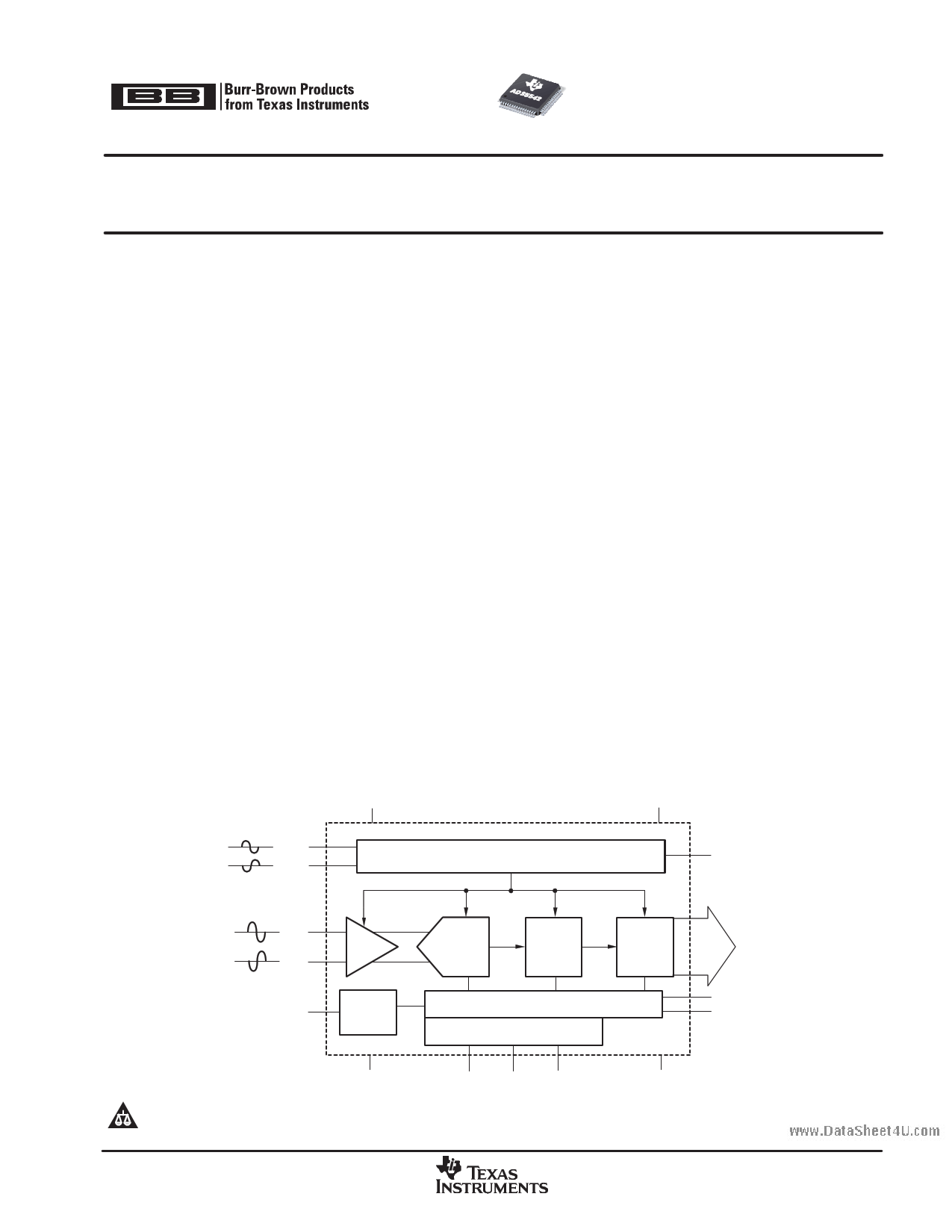
The ADS5542 is a high-performance, 14-bit, 80MSPS analog-to-digital converter (ADC). To provide a complete converter
solution, it includes a high-bandwidth linear sample-and-hold stage (S&H) and internal reference. Designed for
applications demanding the highest speed and highest dynamic performance in very little space, the ADS5542 has
excellent analog power dissipation of 545mW and output buffer power dissipation of 129mW from a 3.3V single-supply
voltage. This allows an even higher system integration density. The provided internal reference simplifies system design
requirements. Parallel CMOS compatible output ensures seamless interfacing with common logic.
The ADS5542 is available in a 64-pin TQFP PowerPAD package and is pin-compatible with the ADS5500, ADS5541,
ADS5520, ADS5521, and ADS5522. This device is specified over the full temperature range of −40°C to +85°C.
AVDD
DRVDD
CLK+
CLK−
Timing Circuitry
CLKOUT
VIN+
VIN−
S&H
CM Internal
Reference
14−Bit
Pipeline
ADC Core
Digital
Error
Correction
Control Logic
Serial Programming Register
Output
Control
D...0
D13
ADS5542
OVR
DFS
AGND
SEN SDATA SCLK
DRGND
Please be aware that an important notice concerning availability, standard warranty, and use in critical applications of Texas Instruments
semiconductor products and disclaimers thereto appears at the end of this data sheet.
PowerPad is a trademark of Texas Instruments. All other trademarks are the property of their respective owners.
PRODUCTION DATA information is current as of publication date. Products
conform to specifications per the terms of Texas Instruments standard warranty.
Production processing does not necessarily include testing of all parameters.
Copyright 2004−2005, Texas Instruments Incorporated
DataSheet4 U .com
www.ti.com
1 page 
www.DataSheet4U.com
ADS5542
www.ti.com
SBAS308A − MAY 2004 − REVISED MARCH 2005
ELECTRICAL CHARACTERISTICS (continued)
Typical values at TA = +25°C, full temperature range is TMIN = −40°C to TMAX = +85°C, AVDD = DRVDD = 3.3V, sampling rate = 80MSPS,
50% clock duty cycle, 3VPP differential clock, and −1dBFS differential input, unless otherwise noted.
PARAMETER
Power Supply
Total supply current, ICC
Analog supply current, IAVDD
Output buffer supply current, IDRVDD
Power dissipation
Standby power
CONDITIONS
fIN = 70MHz
fIN = 70MHz
fIN = 70MHz
Analog only
Output buffer power with 10pF load on
digital output to ground
With clocks running
MIN
TYP MAX
204 230
165 180
39 50
545 594
129 165
180 250
UNIT
mA
mA
mA
mW
mW
mW
DIGITAL CHARACTERISTICS
Valid over full temperature range of TMIN = −40°C to TMAX = +85°C, AVDD = DRVDD = 3.3V, unless otherwise noted.
PARAMETER
Digital Inputs
High-level input voltage, VIH
Low-level input voltage, VIL
High-level input current, IIH
Low-level input current, IIL
Input current for RESET
Input capacitance
Digital Outputs
Low-level output voltage, VOL
High-level output voltage, VOH
Output capacitance
CONDITIONS
CLOAD = 10pF
CLOAD = 10pF
MIN TYP MAX
2.4
0.8
10
10
−20
4
0.3 0.4
2.4 3.0
3
UNIT
V
V
µA
µA
µA
pF
V
V
pF
DataSheet4 U .com
5
5 Page 
www.DataSheet4U.com
ADS5542
www.ti.com
SBAS308A − MAY 2004 − REVISED MARCH 2005
DEFINITION OF SPECIFICATIONS
Analog Bandwidth
The analog input frequency at which the power of the
fundamental is reduced by 3dB with respect to the low
frequency value.
Aperture Delay
The delay in time between the falling edge of the input
sampling clock and the actual time at which the
sampling occurs.
Aperture Uncertainty (Jitter)
The sample-to-sample variation in aperture delay.
Clock Pulse Width/Duty Cycle
The duty cycle of a clock signal is the ratio of the time
the clock signal remains at a logic high (clock pulse
width) to the period of the clock signal. Duty cycle is
typically expressed as a percentage. A perfect
differential sine wave clock results in a 50% duty cycle.
Maximum Conversion Rate
The maximum sampling rate at which certified
operation is given. All parametric testing is performed
at this sampling rate unless otherwise noted.
Minimum Conversion Rate
The minimum sampling rate at which the ADC
functions.
Differential Nonlinearity (DNL)
An ideal ADC exhibits code transitions at analog input
values spaced exactly 1LSB apart. The DNL is the
deviation of any single step from this ideal value,
measured in units of LSBs.
Integral Nonlinearity (INL)
The INL is the deviation of the ADC’s transfer function
from a best fit line determined by a least squares curve
fit of that transfer function, measured in units of LSBs.
Gain Error
The gain error is the deviation of the ADC’s actual input
full-scale range from its ideal value. The gain error is
given as a percentage of the ideal input full-scale range.
Gain error does not account for variations in the internal
reference voltages (see the Electrical Specifications
section for limits on the variation of VREFP and VREFM).
Offset Error
The offset error is the difference, given in number of
LSBs, between the ADC’s actual average idle channel
output code and the ideal average idle channel output
code. This quantity is often mapped into mV.
Temperature Drift
The temperature drift coefficient (with respect to gain
error and offset error) specifies the change per degree
celcius of the parameter from TMIN to TMAX. It is
calcuated by dividing the maximum deviation of the
parameter across the TMIN to TMAX range by the
difference TMAX−TMIN.
Signal-to-Noise Ratio
SNR is the ratio of the power of the fundamental (PS)
to the noise floor power (PN), excluding the power at DC
and the first eight harmonics.
SNR
+
10Log10
PS
PN
SNR is either given in units of dBc (dB to carrier) when
the absolute power of the fundamental is used as the
reference, or dBFS (dB to Full Scale) when the power
of the fundamental is extrapolated to the converter’s
full-scale range.
Signal-to-Noise and Distortion (SINAD)
SINAD is the ratio of the power of the fundamental (PS)
to the power of all the other spectral components
including noise (PN) and distortion (PD), but excluding
DC.
SINAD
+
10Log10
PN
PS
)
PD
SINAD is either given in units of dBc (dB to carrier) when
the absolute power of the fundamental is used as the
reference, or dBFS (dB to Full-Scale) when the power
of the fundamental is extrapolated to the converter’s
full-scale range.
Effective Number of Bits (ENOB)
The ENOB is a measure of a converter’s performance
as compared to the theoretical limit based on
quantization noise.
ENOB
+
SINAD *
6.02
1.76
DataSheet4 U .com
11
11 Page | ||
| Páginas | Total 30 Páginas | |
| PDF Descargar | [ Datasheet ADS5520.PDF ] | |
Hoja de datos destacado
| Número de pieza | Descripción | Fabricantes |
| ADS5520 | (ADS552x) 80MSPS Analog-to-Digital Converter | Burr-Brown Corporation |
| ADS5520 | 12-Bit 125MSPS Analog-to-Digital Converter (Rev. F) | Texas Instruments |
| ADS5521 | (ADS552x) 80MSPS Analog-to-Digital Converter | Burr-Brown Corporation |
| ADS5521 | 12-Bit 105MSPS Analog-to-Digital Converter (Rev. D) | Texas Instruments |
| Número de pieza | Descripción | Fabricantes |
| SLA6805M | High Voltage 3 phase Motor Driver IC. |
Sanken |
| SDC1742 | 12- and 14-Bit Hybrid Synchro / Resolver-to-Digital Converters. |
Analog Devices |
|
DataSheet.es es una pagina web que funciona como un repositorio de manuales o hoja de datos de muchos de los productos más populares, |
| DataSheet.es | 2020 | Privacy Policy | Contacto | Buscar |