|
|
|
PDF ICS9173-01 Data sheet ( Hoja de datos )
| Número de pieza | ICS9173-01 | |
| Descripción | Video Genlock PLL | |
| Fabricantes | Integrated Circuit Systems | |
| Logotipo | ||
Hay una vista previa y un enlace de descarga de ICS9173-01 (archivo pdf) en la parte inferior de esta página. Total 7 Páginas | ||
|
No Preview Available !
www.DataSheet4U.com
Integrated
Circuit
Systems,Inc.
AV 9173 - 01
Video Genlock PLL
General Description
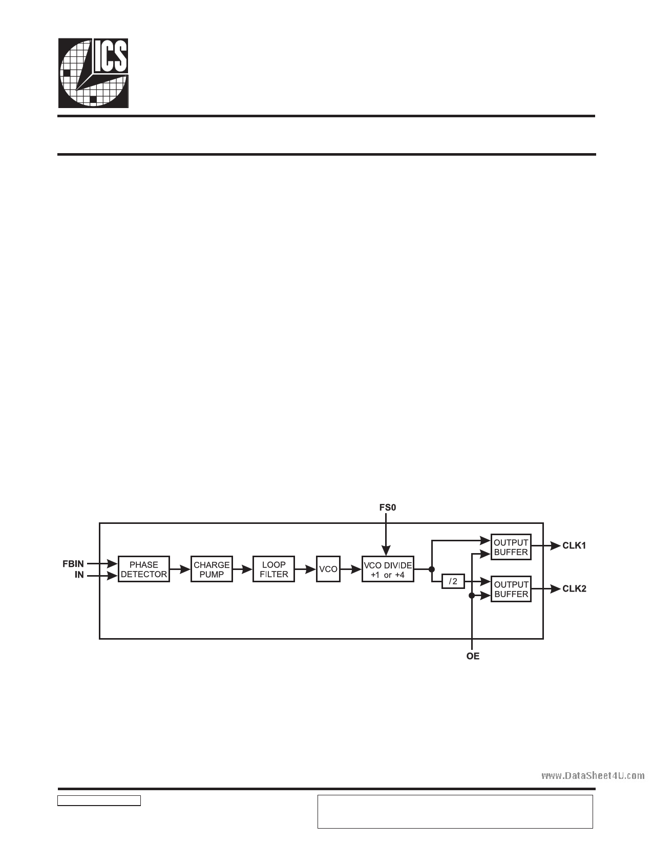
The AV9173-01 provides the analog circuit blocks required
for implementing a video genlock dot (pixel) clock
generator. It contains a phase detector, charge pump, loop
filter, and voltage-controlled oscillator (VCO). By grouping
these critical analog blocks into one IC and utilizing
external digital functions, performance and design
flexibility are optimized as are development time and
system cost.
When used with an external clock divider, the AV9173-01
forms a Phase-Locked Loop configured as a frequency
synthesizer. The AV9173-01 is designed to accept video
horizontal synchronization (h-sync) pulses and produce a
video dot clock. A separated, negative-going sync input
reference pulse is required at pin 2 (IN).
The AV9173-01 is also suited for other clock recovery
applications in such areas as data communications.
Features
• Phase-detector/VCO circuit block
• Ideal for genlock system
• Reference clock range 25 kHz to 1MHz for full
output clock range
• Input clocks down to 12 kHz possible with restricted
output conditions (see Table 1)
• Output clock range 1.25 to 75 MHz
• On-chip loop filter
• Single 5 volt power supply
• Low power CMOS technology
• Small 8-pin DIP or SOIC package
Block Diagram
AV9173-01 Rev D 06/21/05
DataSheet4 U .com
ICS reserves the right to make changes in the device data identified in this
publication without further notice. ICS advises its customers to obtain the latest
version of all device data to verify that any information being relied upon by the
customer is current and accurate.
1 page 
www.DataSheet4U.com
AV9173- 01
Electrical Characteristics
VDD = +5V ±5%, TA = 0°C to 70°C, unless otherwise stated
PARAMETER
Input Clock Rise Time1
Input Clock Fall Time1
Output Rise Time1
Output Rise time1
Output Fall time1
Output Fall time1
Output Duty Cycle1
Jitter, one sigma1
Jitter, absolute1
Jitter, one sigma1
Jitter, absolute1
Line-to-line jitter,1 absolute2
Input Frequency,1 IN or FBIN
CLK1 Frequency1, 3, 4
AC CHARACTERISTICS
SYMBOL
TEST CONDITIONS
ICLKr
ICLKf
tr1 15pF load; 0.8 to 2.0V
tr2
15pF load;
20% to 80% VDD
tf1 15pF load; 2.0 to 0.8V
tf2
15pF load;
80% to 20% VDD
dt
T1s1
Tabs1
T1s2
Tabs2
15pF load
CLK1 frequency≥ 25 MHz
CLK1 frequency≥ 25 MHz
CLK1 frequency< 25 MHz
CLK1 frequency< 25 MHz
TLabs
fi
fCLK1
See allowable fi below:
12 ≤ fi ≤ 14 kHz
14 < fi ≤ 17 kHz
17 < fi ≤ 30 kHz
30 < fi ≤ 35 kHz
35 < fi ≤ 1000 kHz
MIN TYP MAX UNITS
— — 10 ns
— — 10 ns
— 0.6 1.5 ns
— 1.6 3.0 ns
— 1.0 2.0 ns
— 0.9 2.0 ns
40 47 55 %
— 120 250 ps
-400 ±250 400 ps
—— 1 %
—— 2 %
— ±4 — ns
12 — 1000 kHz
44.0 —
75 MHz
30.0 —
75 MHz
25.0 —
75 MHz
15.0 —
75 MHz
10.0 —
75 MHz
Notes:
1. Parameter is guaranteed by design and characterization. Not 100% tested in production.
2. Input Reference Frequency = 25 kHz, Output Frequency = 25 MHz. Jitter measured between adjacent vertical pixels.
3. CLK1 frequency applies for FS = 0. For FS = 1 condition, divide allowable CLK1 range by the factor of 4.
4. An Application Brief (AB01) documents the operation of the AV9173 for low input frequencies. This provides
guidelines for usable output frequencies and feedback ratios required to use inputs below 25 kHz. By following these
guidelines, the AV9173 will operate down to 12 kHz inputs across temperature, voltage and lot-to-lot variation.
DataSheet4 U .com
5
5 Page | ||
| Páginas | Total 7 Páginas | |
| PDF Descargar | [ Datasheet ICS9173-01.PDF ] | |
Hoja de datos destacado
| Número de pieza | Descripción | Fabricantes |
| ICS9173-01 | Video Genlock PLL | Integrated Circuit Systems |
| Número de pieza | Descripción | Fabricantes |
| SLA6805M | High Voltage 3 phase Motor Driver IC. |
Sanken |
| SDC1742 | 12- and 14-Bit Hybrid Synchro / Resolver-to-Digital Converters. |
Analog Devices |
|
DataSheet.es es una pagina web que funciona como un repositorio de manuales o hoja de datos de muchos de los productos más populares, |
| DataSheet.es | 2020 | Privacy Policy | Contacto | Buscar |