|
|
|
PDF ICS94235 Data sheet ( Hoja de datos )
| Número de pieza | ICS94235 | |
| Descripción | Programmable System Clock Chip | |
| Fabricantes | Integrated Circuit System | |
| Logotipo | ||
Hay una vista previa y un enlace de descarga de ICS94235 (archivo pdf) en la parte inferior de esta página. Total 19 Páginas | ||
|
No Preview Available !
www.DataSheet4U.com
Integrated
Circuit
Systems, Inc.
ICS94235
Programmable System Clock Chip for AMD - K7 processor
Recommended Application:
ALI 1647 style chipset
Output Features:
• 1 - Differential pair open drain CPU clocks
• 1 - Single-ended open drain CPU clock
• 13 - SDRAM @ 3.3V
• 7 - PCI @ 3.3V
• 2 - AGP @ 3.3V
• 1 - 48MHz, @3.3V
• 1 - REF @ 3.3V, (selectable strength) through I2C
Features:
• Programmable ouput frequency
• Programmable ouput rise/fall time
• Programmable CPU, SDRAM, PCI and AGP skew
• Real time system reset output
• Spread spectrum for EMI control typically
by 7dB to 8dB, with programmable spread percentage
• Watchdog timer technology to reset system
if over-clocking causes malfunction
• Uses external 14.318MHz crystal
Skew Specifications:
• CPUT - CPUC: <250ps
• PCI - PCI: <500ps
• CPU - SDRAM: <350ps
• SDRAM - SDRAM: <250ps
• AGP - AGP: <250ps
• AGP - PCI: <750ps
• CPU - PCI: <3ns
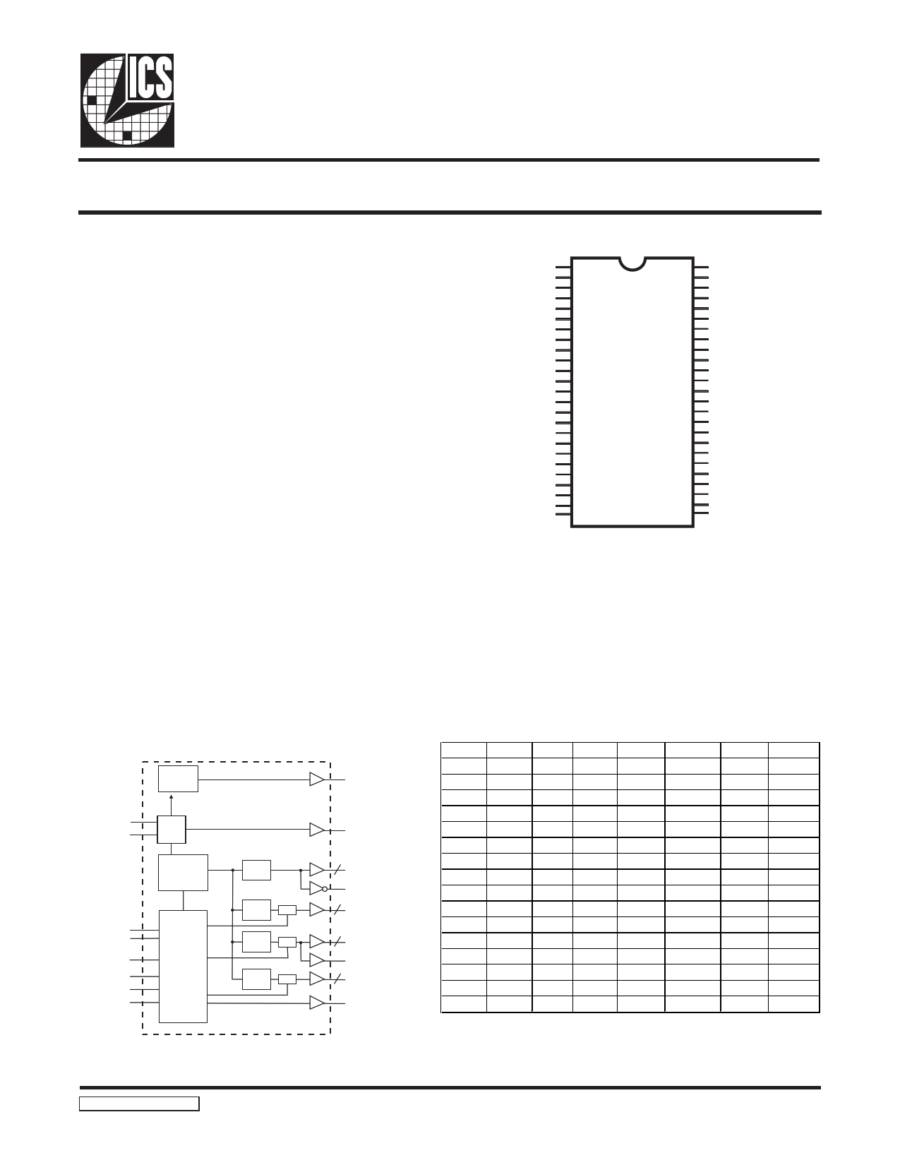
Pin Configuration
RESET#
*PD#
GND
X1
X2
AVDD
**FS0/REF0
VDD
**FS1/AGP0
AGP1
GND
*FS2/PCICLK_F
PCICLK0
PCICLK1
PCICLK2
GND
VDD
*MODE/PCICLK3
PCICLK4
PCICLK5
AVDD48
**FS3/48MHz
GND
SCLK
1
2
3
4
5
6
7
8
9
10
11
12
13
14
15
16
17
18
19
20
21
22
23
24
48 GND
47 CPUCLKT0
46 CPUCLKC0
45 CPUCLKT1
44 SDATA
43 SDRAM0
42 SDRAM1
41 GND
40 VDD
39 SDRAM2
38 SDRAM3
37 SDRAM4
36 SDRAM5
35 VDD
34 GND
33 SDRAM6
32 SDRAM7
31 SDRAM8
30 SDRAM9
29 GND
28 VDD
27 SDRAM10(PCI_STOP#)*
26 SDRAM11
25 SDRAM12
48-Pin 300mil SSOP &
240mil TSSOP package
Notes:
REF0 could be 1X or 2X strength controlled by I2C.
* Internal Pull-up Resistor of 120K to VDD
** Internal pull-down of 120K to GND.
Block Diagram
PLL2
X1 XTAL
X2 OSC
PLL1
Spread
Spectrum
CPU
DIVDER
SDATA
SCLK
FS (3:0)
PD#
PCI_STOP#
MODE
Control
Logic
Config.
Reg.
SDRAM
DIVDER
Stop
PCI
DIVDER
Stop
AGP
DIVDER
Stop
www.DataSheet4U.com
48MHz
REF0
CPUCLKT (1:0)
2
CPUCLKC0
SDRAM (12:0)
13
PCICLK (5:0)
6
PCICLK_F
AGP (1:0)
2
RESET#
Functionality
FS3
0
0
0
0
0
0
0
0
1
1
1
1
1
0
1
1
FS2
0
0
0
0
1
1
1
1
0
0
0
0
1
1
1
1
FS1
0
0
1
1
0
0
1
1
0
0
1
1
0
0
1
1
FS0
0
1
0
1
0
1
0
1
0
1
0
1
0
1
0
1
CPU SDRAM
66.66 66.66
66.66 100.00
100.00 66.66
100.00 100.00
100.00 133.33
120.00 120.00
133.33 100.00
133.33 133.33
90.00 90.00
100.90 100.90
100.00 66.66
100.00 100.00
100.00 133.33
126.00 126.00
133.33 100.00
133.33 133.33
PCI
33.33
33.33
33.33
33.33
33.33
30.00
33.33
33.33
30.00
33.63
33.33
33.33
33.33
31.50
33.33
33.33
Power Groups
AVDD = Xtal, Core PLL
AVDD48 = 48MHz, Fixed PLL
AGP
66.66
66.66
66.66
66.66
66.66
60.00
66.66
66.66
60.00
67.27
66.66
66.66
66.66
63.00
66.66
66.66
94235 Rev A 01/17/02
Third party brands and names are the property of their respective owners.
1 page 
www.DataSheet4U.com
ICS94235
Brief I2C registers description for ICS94235
Programmable System Frequency Generator
Register Name
Functionality & Frequency
Select Register
Output Control Registers
Byte
0
1-6
D es crip tion
Output frequency, hardware / I2C
frequency select, spread spectrum &
output enable control register.
Active / inactive output control
registers/latch inputs read back.
PWD Default
See individual
byte description
See individual
byte description
Vendor ID & Revision ID
R egis ters
7
Byte 11 bit[7:4] is ICS vendor id - 1001.
Other bits in this register designate device
revision ID of this part.
See individual
byte description
Byte Count
Read Back Register
Writing to this register will configure
8 byte count and how many byte will be
read back. Do not write 00H to this byte.
08H
Watchdog Timer
Count Register
Writing to this register will configure the
9 number of seconds for the watchdog
timer to reset.
10H
Watchdog Control Registers 10 Bit [6:0]
VCO Control Selection Bit 10 Bit [7]
Watchdog enable, watchdog status and
programmable ’safe’ frequency’ can be
configured in this register.
This bit select whether the output
frequency is control by hardware/byte 0
configurations or byte 11&12
programming.
000,0000
0
VCO Frequency Control
R egis ters
11-12
These registers control the dividers ratio
into the phase detector and thus control
the VCO output frequency.
Depended on
hardware/byte 0
configuration
Spread Spectrum Control
R egis ters
13-14
These registers control the spread
percentage amount.
Depended on
hardware/byte 0
configuration
Group Skews Control
R egis ters
15-16
Increment or decrement the group skew
amount as compared to the initial skew.
See individual
byte description
Output Rise/Fall Time
Select Registers
17-20
These registers will control the output
rise and fall time.
See individual
byte description
Notes:
1. The ICS clock generator is a slave/receiver, I2C component. It can read back the data stored in the latches for
verification. Readback will support standard SMBUS controller protocol. The number of bytes to readback is
defined by writing to byte 8.
2. When writing to byte 11 - 12, and byte 13 - 14, they must be written as a set. If for example, only byte 14 is written
but not 15, neither byte 14 or 15 will load into the receiver.
3. The data transfer rate supported by this clock generator is 100K bits/sec or less (standard mode)
4. The input is operating at 3.3V logic levels.
5. The data byte format is 8 bit bytes.
6. To simplify the clock generator I2C interface, the protocol is set to use only Block-Writes from the controller. The
bytes must be accessed in sequential order from lowest to highest byte with the ability to stop after any complete
www.bDytae thaaSs bheeenettr4anUsf.ecrroedm. The Command code and Byte count shown above must be sent, but the data is ignored
for those two bytes. The data is loaded until a Stop sequence is issued.
7. At power-on, all registers are set to a default condition, as shown.
Third party brands and names are the property of their respective owners.
5
5 Page 
www.DataSheet4U.com
ICS94235
Absolute Maximum Ratings
Supply Voltage . . . . . . . . . . . . . . . . . . . . . . . . . . . . 5.5V
Logic Inputs . . . . . . . . . . . . . . . . . . . . . . . . . . . . . . GND 0.5 V to VDD +0.5 V
Ambient Operating Temperature . . . . . . . . . . . . . 0°C to +70°C
Storage Temperature . . . . . . . . . . . . . . . . . . . . . . . 65°C to +150°C
Stresses above those listed under Absolute Maximum Ratings may cause permanent damage to the device. These ratings are
stress specifications only and functional operation of the device at these or any other conditions above those listed in the
operational sections of the specifications is not implied. Exposure to absolute maximum rating conditions for extended periods
may affect product reliability.
Electrical Characteristics - Input/Supply/Common Ouput Parameters.
TA = 0 - 70º C; Supply Voltage VDD = 3.3 V +/-5% (unless otherwise stated)
PARAMETER
SYMBOL
CONDITIONS
MIN
Input High Voltage
VIH
2
Input Low Voltage
VIL
VSS-0.3
Input High Current
IIH VIN = VDD
TYP MAX UNITS
VDD+0.3 V
0.8 V
5 uA
Input Low Current
IIL1
VIN = 0 V; Inputs with no pull-up resistors
-5
uA
Input Low Current
IIL2 VIN = 0 V; Inputs with pull-up resistors -200
uA
Operating
Supply Current
IDD3.3OP66
IDD3.3OP100
CL = 0 pF; Select @ 66MHz
CL = 0 pF; Select @ 66MHz
180 mA
Power Down
Input frequency
IDD3.3OP133
PD
Fi
CL = 0 pF; Select @ 133MHz
VDD = 3.3 V;
600 uA
12 14.318 16
MHz
Input Capacitance1
CIN Logic Inputs
CINX X1 & X2 pins
5 pF
27 45 pF
Clk Stabilization1
TSTAB
From VDD = 3.3 V to 1% target Freq.
3 ms
Skew1
tAGP-PCI
tCPU-SDRAM
VT = 50%
tCPU-PCI
1Guaranteed by design, not 100% tested in production.
300 750
200 350
2.67 3
ps
ns
www.DataSheet4U.com
Third party brands and names are the property of their respective owners.
11
11 Page | ||
| Páginas | Total 19 Páginas | |
| PDF Descargar | [ Datasheet ICS94235.PDF ] | |
Hoja de datos destacado
| Número de pieza | Descripción | Fabricantes |
| ICS94235 | Programmable System Clock Chip | Integrated Circuit System |
| ICS94236 | Programmable System Clock Chip | Integrated Circuit System |
| Número de pieza | Descripción | Fabricantes |
| SLA6805M | High Voltage 3 phase Motor Driver IC. |
Sanken |
| SDC1742 | 12- and 14-Bit Hybrid Synchro / Resolver-to-Digital Converters. |
Analog Devices |
|
DataSheet.es es una pagina web que funciona como un repositorio de manuales o hoja de datos de muchos de los productos más populares, |
| DataSheet.es | 2020 | Privacy Policy | Contacto | Buscar |