|
|
|
PDF ICS94228 Data sheet ( Hoja de datos )
| Número de pieza | ICS94228 | |
| Descripción | Programmable System Clock Chip | |
| Fabricantes | Integrated Circuit Systems | |
| Logotipo | ||
Hay una vista previa y un enlace de descarga de ICS94228 (archivo pdf) en la parte inferior de esta página. Total 17 Páginas | ||
|
No Preview Available !
www.DataSheet4U.com
Integrated
Circuit
Systems, Inc.
ICS94228
Programmable System Clock Chip for AMD - K7™ processor
Recommended Application:
VIA KT266 style chipset
Output Features:
• 1 - Differential pair open drain CPU clocks @ 2.7V
• 1 - Differential pair push-pull CPU clocks @ 2.5V
• 11 - PCI including 1 free running and 1 early @ 3.3V
• 1 - 48MHz, @ 3.3V fixed
• 1 - 24/48MHz @ 3.3V
• 3 - REF @ 3.3V, 14.318MHz.
Features:
• Programmable output frequency.
• Programmable output rise/fall time.
• Programmable slew and skew control for CPUCLK,
PCICLK, AGP, REF, 48MHz and 24_48MHz.
• Real time system reset output.
• Spread spectrum for EMI control typically
by 7dB to 8dB, with programmable spread
percentage.
• Watchdog timer technology to reset system
if over-clocking causes malfunction.
• Uses external 14.318MHz crystal.
Skew Specifications:
• CPU - CPU: <200ps
• PCI - PCI: <500ps
• CPU (early - PCI: min=1.0ns, max=2.6ns
• CPU cycle to cycle jitter: <250ps
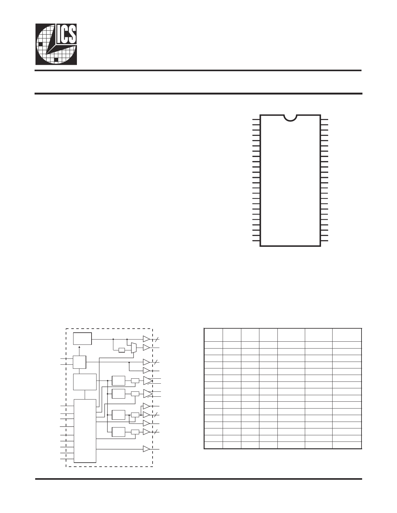
Pin Configuration
VDDREF
GND
X1
X2
AVDD48
*FS2/48MHz
*FS3/24_48MHz
GND
PCICLK_F
*SEL24_48#/PCICLK0
PCICLK1
GND
PCICLK2
PCICLK3
VDDPCI
PCICLK4
PCICLK5
PCICLK6
GND
PCICLK7
PCILCK8
PCICLK9_E
VDDPCI
SRESET#
1
2
3
4
5
6
7
8
9
10
11
12
13
14
15
16
17
18
19
20
21
22
23
24
48 REF0/FS0*
47 REF1/FS1*
46 REF_F
45 REF_STOP#*
44 AGP_STOP#*
43 GND
42 CPUCLKT0
41 CPUCLKC0
40 VDDL
39 CPUCLK_CST0
38 CPUCLK_CSC0
37 GND
36 CPU_STOP#*
35 PCI_STOP#*
34 PD#*
33 AVDD
32 AGND
31 SDATA
30 SCLK
29 GND
28 AGP2
27 AGP1
26 AGP0
25 VDDAGP
48-Pin 300mil SSOP
* Internal Pull-up Resistor of 120K to VDD
Block Diagram
PLL2
X1 XTAL
X2 OSC
/2
PLL1
Spread
Spectrum
CPU
DIVDER
CPU
DIVDER
Stop
Stop
SEL24_48#
SDATA
SCLK
Control
PCI
DIVDER
FS (3:0)
PD#
Logic
AGP
DIVDER
PCI_STOP#
CPU_STOP#
Config.
AwGPw_STwOP.#DataShReeg.et4U.com
REF_STOP#
Stop
Stop
48MHz (1:0)
2
24_48MHz
2 REF (1:0)
REF_F
CPUCLKT0
CPUCLKC0
CPUCLK_CST0
CPUCLK_CSC0
PCICLK9_E
9 PCICLK (8:0)
PCICLK_F
AGP (2:0)
3
SRESET#
Functionality
FS3 FS2 FS1 FS0
0000
000 1
0 0 10
00 11
0 10 0
0 10 1
0 1 10
0 111
10 0 0
10 0 1
10
10
10 1 1
1 10 0
1 10 1
1 1 10
1111
CPU
(MHz)
233.33
220.00
210.00
200.00
190.00
180.00
170.00
150.00
140.00
120.00
110.00
66.67
200.00
166.67
100.00
133.33
AGP
(MHz)
77.78
73.33
70.00
66.67
76.00
72.00
68.00
75.00
70.00
60.00
66.00
66.67
66.67
66.67
66.67
66.67
PCICLK
(MHz)
38.88
36.67
35.00
33.33
38.00
36.00
34.00
37.50
35.00
30.00
33.00
33.33
33.33
33.33
33.33
33.33
0447E—05/07/04
1 page 
www.DataSheet4U.com
ICS94228
Brief I2C registers description for ICS94228
Programmable System Frequency Generator
Register Name
Functionality &
Frequency Select
Register
Byte
0
Output Control Registers 1, 2, 3
Vendor ID & Revision ID
Registers
5, 6, 7
Byte Count
Read Back Register
Watchdog Enable
Register
8
4
Description
Output frequency, hardware / I2C
frequency select, spread spectrum &
output enable control register.
Active / inactive output control
registers/latch inputs read back.
Byte 11 bit[7:4] is ICS vendor id -
1001. Other bits in this register
designate device revision ID of this
part.
Writing to this register will configure
byte count and how many byte will
be read back. Do not write 00H to
this byte.
Writing to this register will configure
the number of seconds for the
watchdog timer to reset.
PWD Default
See individual
byte
description
See individual
byte
description
See individual
byte
description
08H
10H
Watchdog Control
Registers
Watchdog enable, watchdog status
and programmable 'safe' frequency'
can be configured in this register.
000,0000
VCO Control Selection
Bit
4, 5
VCO Frequency Control
Registers
9, 10
This bit select whether the output
frequency is control by
hardware/byte 0 configurations or
byte 11&12 programming.
These registers control the dividers
ratio into the phase detector and
thus control the VCO output
frequency.
0
Depended on
hardware/byte
0 configuration
Spread Spectrum
Control Registers
11, 12
These registers control the spread
percentage amount.
Depended on
hardware/byte
0 configuration
Group Skews Control
Registers
Output Rise/Fall Time
Select Registers
13, 14
15, 16
Increment or decrement the group
skew amount as compared to the
initial skew.
These registers will control the
output rise and fall time.
See individual
byte
description
See individual
byte
description
Notes:
1. The ICS clock generator is a slave/receiver, I2C component. It can read back the data stored in the latches
for verification. Readback will support standard SMBUS controller protocol. The number of bytes to
readback is defined by writing to byte 8.
2. When writing to byte 11 - 12, and byte 13 - 14, they must be written as a set. If for example, only byte
14 is written but not 15, neither byte 14 or 15 will load into the receiver.
3. The data transfer rate supported by this clock generator is 100K bits/sec or less (standard mode)
4. The input is operating at 3.3V logic levels.
5. The data byte format is 8 bit bytes.
6. To simplify the clock generator I2C interface, the protocol is set to use only Block-Writes from the
controller. The bytes must be accessed in sequential order from lowest to highest byte with the ability to
stop after any complete byte has been transferred. The Command code and Byte count shown above must
www.bDeasteanSt, hbuetetht4e Uda.tcaoismignored for those two bytes. The data is loaded until a Stop sequence is issued.
7. At power-on, all registers are set to a default condition, as shown.
0447E—05/07/04
5
5 Page 
www.DataSheet4U.com
ICS94228
Electrical Characteristics - REF
TA = 0 - 70°C; VDD = 3.3 V +/-5%; CL = 20 pF (unless otherwise stated)
PARAMETER SYMBOL
CONDITIONS
Output High Voltage VOH5 IOH = -12 mA
Output Low Voltage VOL5 IOL = 9 mA
Output High Current
IOH5 VOH = 2.0 V
Output Low Current
Rise Time1
Fall Time1
Duty Cycle1
IOL5 VOL = 0.8 V
tr5 VOL = 0.4 V, VOH = 2.4 V
tf5 VOH = 2.4 V, VOL = 0.4 V
dt5 VT = 1.5V
1Guaranteed by design, not 100% tested in production.
MIN TYP MAX UNITS
2.4 V
0.4 V
-22 mA
16 mA
1.3 4 ns
1.4 4 ns
45 54 57 %
Electrical Characteristics - CPUCLK (Open Drain)
TA = 0 - 70°C; VDD = 3.3 V +/-5%; VDDL=2.5V+/-5%; CL = 20 pF (unless otherwise stated)
PARAMETER
SYMBOL CONDITIONS
MIN TYP
MAX
UNITS
Output Impedance
Output High Voltage
ZO
VOH2B
VO = VX
Termination to
Vpull-up(external)
1
W
1.2 V
Output Low Voltage
VOL2B
Termination to
Vpull-up(external)
0.4 V
Output Low Current
Rise Time1, CPUCLK
Fall Time1, CPUCLK
Differential voltage-AC1
IOL2B
tr2B
tf2B
VDIF
VOL = 0.3V
VOL = 20%, VOH = 80%
VOH = 80%, VOL=20%
Note 2
18 mA
2.2 2.5
ns
1.3 2.0
ns
0.4
Vpullup(external)
V
+ 0.6
Differential voltage-DC1
Differential Crossover
Voltage1 CPUCLK(Open Drain)
Duty Cycle1
Skew1
Jitter, Cycle-to-cycle1,
CPUCLK
VDIF
VX
dt2B
tsk2B
tjcyc-cyc2B
Note 2
Note 3
VT = 50%
VT = 50%
VT = VX
0.2 Vpullup(external)
+ 0.6
1.2 1.4
1.7
45 50
140
55
200
150 250
V
V
%
ps
Notes:
1 - Guaranteed by design, not 100% tested in production.
2 - VDIF specifies the minimum input differential voltages (VTR-VCP) required for switching, where VTR is the "tr
3 - Vpullup(external) = 2.7V, Min = Vpullup(external)/2-150mV; Max=(Vpullup(external)/2)+150mV
www.DataSheet4U.com
0447E—05/07/04
11
11 Page | ||
| Páginas | Total 17 Páginas | |
| PDF Descargar | [ Datasheet ICS94228.PDF ] | |
Hoja de datos destacado
| Número de pieza | Descripción | Fabricantes |
| ICS94222 | Programmable System Frequency Generator for PII/III�� | ETC |
| ICS94225 | AMD-K7TM System Clock Chip | Integrated Circuit Solution |
| ICS94228 | Programmable System Clock Chip | Integrated Circuit Systems |
| ICS94229 | Programmable System Clock Chip | Integrated Circuit Systems |
| Número de pieza | Descripción | Fabricantes |
| SLA6805M | High Voltage 3 phase Motor Driver IC. |
Sanken |
| SDC1742 | 12- and 14-Bit Hybrid Synchro / Resolver-to-Digital Converters. |
Analog Devices |
|
DataSheet.es es una pagina web que funciona como un repositorio de manuales o hoja de datos de muchos de los productos más populares, |
| DataSheet.es | 2020 | Privacy Policy | Contacto | Buscar |