|
|
|
PDF V360EPC Data sheet ( Hoja de datos )
| Número de pieza | V360EPC | |
| Descripción | Local Bus to PCI Bridge | |
| Fabricantes | QuickLogic | |
| Logotipo | ||
Hay una vista previa y un enlace de descarga de V360EPC (archivo pdf) en la parte inferior de esta página. Total 18 Páginas | ||
|
No Preview Available !
V360EPC Rev. A0 / A1
LOCAL BUS TO PCI BRIDGE
omFOR DE-MULTIPLEXED A/D PROCESSORS
t4U.c• Glueless interface to i960Cx/Hx and
AMD29030/40 processors
ee• Configurable for primary master, bus master or
htarget operation.
S• Type 0 and type 1 configuration cycles.
ta• Up to 1Kbyte burst access on PCI or local.
a m• Large, 640-byte FIFOs using V3’s unique
.DDYNAMIC BANDWIDTH ALLOCATION™ architecture
w o• 64-byte read FIFO per aperture.
ww .c• Enhanced support for 8/16-bit local bus devices
with programmable region sizes.
• 3.3 volt support
U• Dual bi-directional address space remapping
t4• Fully compliant with PCI 2.1 specification
• On-the-fly byte order (endian) conversion
• I2O ATU and messaging unit including
hardware controlled circular queues
• 2 channel DMA controller plus multiprocessor
DMA chaining and demand mode DMA
• Hot swapping capability
• 16 8-bit bi-directional mailbox registers with
doorbell interrupts
• Flexible PCI and local interrupt management
• Optional power-on serial EEPROM initialization
• 33MHz and 50MHz local bus versions
• Industrials Temperature Grade -40 to +85’C
• Low cost 160-pin EIAJ PQFP package
V360EPC provides the highest performance,
emost flexible, and most economical method to
directly connect i960Cx/Hx or AMD2930/40
eprocessors to the PCI bus. As a generic solution
for 32-bit de-multiplexed local bus applications,
hV360EPC is also a suitable candidate for a
variety of high-performance applications based
Son Motorola, IBM, DEC and Hitachi embedded
processors - where a minimal amount of glue
talogic is needed.
V360EPC is the second generation of V3’s I2O
aready PCI bridges - fully backward compatible
with V962PBC and V292PBC Rev B2 devices -
and is supporting powerful features like Hot
.DSwap and DMA chaining. The PCI bus can be
mrun at full 33MHz, independent of local bus clock
w .corate. The overall throughput of the system is
dramatically improved by increasing the FIFO
depths and utilizing the unique DYNAMIC
BANDWIDTH ALLOCATION™ architecture.
Access to the PCI bus can be performed through
two programmable address apertures. Two more
apertures are provided for PCI-to-local bus
accesses. There are 64-bytes of read FIFOs in
each direction, 32-bytes dedicated for each
aperture.
Two high-performance DMA channels with
chaining and demand mode capabilities provide
a powerful data transfer engine for bulk data
transfers. Mailbox registers and flexible PCI
interrupt controllers are also included to provide
a simple mechanism to emulate PCI device
control ports. The part is available in 160-pin low
cost PQFP packages.
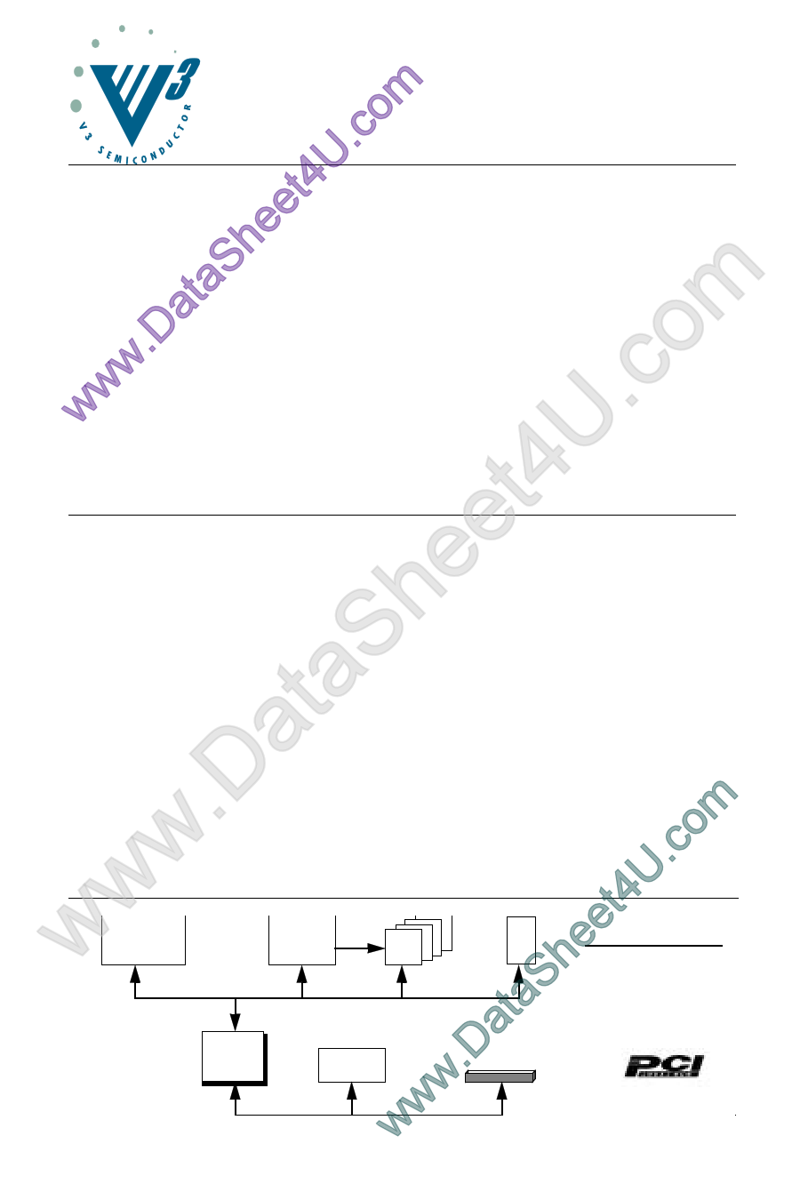
w et4Ui960Cx/Hx
eCPU
V 96BMC
MEMORY
CONTROL
D
R
A
M
ROM TYPICAL APPLICATION
w ataShV360EPC
.DLOCAL TO
PCI BRIDGE
PCI
PERIPHERAL
PCI SLOT or EDGE CONNECTOR
wwwCopyright © 1998, V3 Semiconductor Corp.
V360EPC Data Sheet Rev 1.2
1
V3 Semiconductor reserves the right to change the specifications of this product without notice.
V360EPC and V96BMC are trademarks of V3 Semiconductor. All other trademarks are the property of their respective owners.
1 page 
V360EPC
Table 3: Signal Descriptions (cont’d)
Configuration
Signal
Type
R Description
RDIR
I
Reset direction. Tie low to drive PRST out and LRST in, high to
drive LRST out and PRST in.
EN5V
I
Selects 5V (EN5V driven low) or 3.3V (EN5V driven high) device
operation modes.
Power and Ground Signals
Signal
Type
R Description
VCC
-
POWER leads intended for external connection to a VCC board
plane.
GND
-
GROUND leads intended for external connection to a GND board
plane.
a. R indicates state during reset.
b. Applies to AMD29030/40 mode.
c. Applies to i960Cx/Hx mode.
2.1 Test Mode Pins
Several device pins are used during manufacturing test to put the V360EPC device into various test
modes. These pins must be maintained at proper levels during reset to insure proper operation.
This is typically handled through pull-up or pull-down resistors (typically 1K to 10K) on the signal pins if
they are not guaranteed to be at the proper level during reset. Table 4 below shows the reset states for
test mode pins:
Table 4: RESET State for Test Mode Pins
Mode
i960Cx/Hx
AMD2930/40
Pin 134
Pull-Up
Pull-Down
Pin 135
Pull-Up
Pull-Up
Pin 153
Pull-Up
Pull-Up
Copyright © 1998, V3 Semiconductor Corp.
V360EPC Data Sheet Rev 1.2
5
5 Page 
V360EPC
Table 8: PCI Bus Signals DC Operating Specifications
Symbol
Parameter
Condition
Min Max Units Notes
CCLK PCLK pin capacitance
5 12 pF
CIDSEL IDSEL pin capacitance
8 pF 4
LPIN Pin inductance
20 nH
Notes:
1. Input leakage currents include high impedance output leakage for all bi-directional buffers with tri-state out-
puts.
2. Signals without pull-up resistors have greater than 3mA low output current. Signals requiring pull resistors
have greater than 6mA output current. The latter include FRAME, TRDY, IRDY, STOP, SERR, PERR.
3. Absolute maximum pin capacitance for a PCI unit is 10pF (except for CLK).
4. Lower capacitance on this input-only pin allows for non-resistive coupling to AD[xx].
3.2 Local Bus DC Specifications
Table 9: Local Bus Signals DC Operating Specifications for Vcc = 5 volt
Symbol
Description
VIL
VIH
IIL
IIH
VOL4
Low level input voltage
High level input voltage
Low level input current
High level input current
Low level output voltage for 4 mA
outputs and I/O pins
VOH4
High level output voltage for 4 mA
outputs and I/O pins
IOZL
IOZH
Low level float input leakage
High level float input leakage
ICC (max) Maximum supply current
ICC (typ) Typical supply current
CIO Input and output capacitance
Conditions
VCC = 4.75V
VCC = 5.25V
VIN=GND, VCC=5.25V
VIN = VCC = 5.25V
Min Max Units
0.8 V
2.0 V
-10 µA
10 µA
IOL = -4 mA
0.4 V
IOH = 4 mA
2.4
V
VIN = GND
VIN = VCC
VCC = 5.25V
PCLK = LCLK = 33MHz
VCC = 5.0V
PCLK = LCLK = 33MHz
-10
10
150
120
10
µA
µA
mA
mA
pF
Copyright © 1998, V3 Semiconductor Corp.
V360EPC Data Sheet Rev 1.2
11
11 Page | ||
| Páginas | Total 18 Páginas | |
| PDF Descargar | [ Datasheet V360EPC.PDF ] | |
Hoja de datos destacado
| Número de pieza | Descripción | Fabricantes |
| V360EPC | Local Bus to PCI Bridge | QuickLogic |
| Número de pieza | Descripción | Fabricantes |
| SLA6805M | High Voltage 3 phase Motor Driver IC. |
Sanken |
| SDC1742 | 12- and 14-Bit Hybrid Synchro / Resolver-to-Digital Converters. |
Analog Devices |
|
DataSheet.es es una pagina web que funciona como un repositorio de manuales o hoja de datos de muchos de los productos más populares, |
| DataSheet.es | 2020 | Privacy Policy | Contacto | Buscar |