|
|
|
PDF CGB240B Data sheet ( Hoja de datos )
| Número de pieza | CGB240B | |
| Descripción | 2-Stage Bluetooth & WLAN InGaP HBT Power Amplifier | |
| Fabricantes | TriQuint Semiconductor | |
| Logotipo | ||
Hay una vista previa y un enlace de descarga de CGB240B (archivo pdf) en la parte inferior de esta página. Total 19 Páginas | ||
|
No Preview Available !
CGB 240B
Datasheet
2-Stage Bluetooth & WLAN InGaP HBT Power Amplifier
Description:
The CGB240B GaAs power amplifier MMIC has been
especially developed for wireless LAN applications in the
2.4 - 2.5 GHz ISM band, compliant with IEEE 802.11b
standards. The chip is also fully compliant with Bluetooth
class 1 applications and thus can be used in dual-mode
(Bluetooth/WLAN) applications, too.
While providing an effective channel power of 22dBm, the
ACPR is better than -33dB relative to the sinx/x spectral
peak of an IEEE802.11b–modulated TX signal. Each
CGB240B chip is individually tested for IP3, resulting in
guaranteed ACPR performance.
In a Bluetooth class 1 system, the CGB240B’s high power
added efficiency (up to 50%) and single positive supply
operation makes the device ideally suited for handheld
applications. The CGB240B delivers 23 dBm output power
at a supply voltage of 3.2 V, with an overall PAE of 50% in
saturated mode. The output power can be adjusted using
an analog control voltage (VCTR). Simple external input-,
interstage-, and output matching circuits are used to adapt
to the different requirements of linearity and harmonic
suppression in various applications2-stage InGaP HBT
power amplifier for WLAN and Bluetooth applications.
Features:
• Pout = +23dBm at 3.2 V
• ACPR / IP3 tested to be compliant with IEEE802.11b
standard
• Fully compliant with Bluetooth requirements (dual-mode
use)
• Single voltage supply
• Wide operating voltage range 2.0 - 5.5 V
• Analog power control with four power steps
• Easy external matching concept
Applications:
• WLAN
• IEEE 802.11a
• Bluetooth Class 1
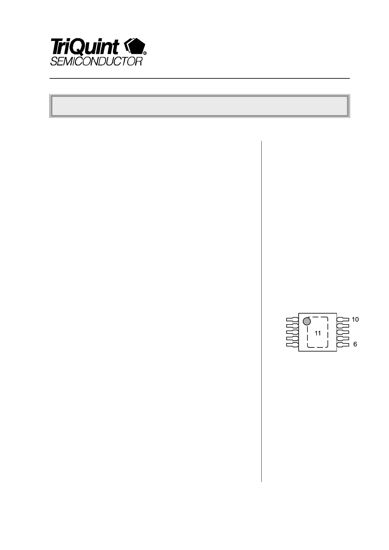
Package Outline:
1
5
P-TSSOP-10-2
Pin configuration:
1 & 2:
Vc1
3: RFin
4, 5, & 10:
NC
6: Vcntrl1
7: Vcntro2
8 & 9:
Vc2
11 (paddle) GND
For More Information, Please Visit www.triquint.com
Rev 1.3, July 14th, 2003
pg. 1/20
1 page 
CGB240B Datasheet
Typical S–Parameters for IEEE802.11b Operation
TA = 25 °C; VCC = 3.3 V; VCTR = 3,3 V; Port 1: RF In (Pin 3); Port 2: RF Out (Pins 8/9)
PIN < - 10 dBm; Interstage match and DC bias circuit according to application note 1.
Frequency
(GHz)
0,2
0,4
0,6
0,8
1
1,2
1,4
1,6
1,8
2
2,2
2,3
2,4
2,5
2,6
2,8
3
3,2
3,4
3,6
3,8
4
S11
Real
(x1)
0,31
0,29
0,17
0,04
-0,06
-0,16
-0,27
-0,37
-0,47
-0,57
-0,67
-0,70
-0,73
-0,74
-0,74
-0,69
-0,63
-0,53
-0,41
-0,30
-0,21
-0,12
Imag
(x1)
-0,10
-0,22
-0,31
-0,34
-0,35
-0,35
-0,34
-0,32
-0,27
-0,22
-0,11
-0,04
0,04
0,12
0,21
0,36
0,51
0,63
0,72
0,77
0,80
0,82
Note: Table available as S2P file.
S21
Real
(x1)
10,46
2,51
6,10
8,57
9,25
8,65
7,17
5,11
2,70
-0,36
-3,71
-5,32
-6,88
-8,18
-9,23
-10,40
-10,94
-10,59
-9,16
-7,78
-6,26
-4,62
Imag
(x1)
-2,89
0,20
1,73
-0,46
-3,27
-6,18
-8,66
-10,46
-11,63
-12,67
-12,10
-11,58
-10,53
-9,49
-8,10
-4,99
-2,12
0,72
3,05
4,53
5,45
6,47
S12
Real
(x1)
0,0002
0,0001
-0,0004
-0,0001
0,0003
0,0004
0,0007
0,0008
0,0012
0,0026
0,0025
0,0026
0,0026
0,0034
0,0033
0,0044
0,0053
0,0061
0,0084
0,0088
0,0105
0,0119
Imag
(x1)
0,0001
0,0003
0,0015
0,0017
0,0022
0,0028
0,0030
0,0034
0,0043
0,0046
0,0051
0,0049
0,0048
0,0051
0,0055
0,0059
0,0066
0,0067
0,0070
0,0050
0,0051
0,0033
S21
Real
(x1)
-0,47
-0,60
-0,61
-0,60
-0,59
-0,57
-0,56
-0,55
-0,54
-0,50
-0,47
-0,46
-0,44
-0,43
-0,41
-0,35
-0,30
-0,24
-0,17
-0,12
-0,04
0,06
Imag
(x1)
-0,02
0,05
0,11
0,16
0,20
0,22
0,24
0,26
0,30
0,32
0,34
0,36
0,37
0,39
0,41
0,44
0,48
0,50
0,50
0,51
0,51
0,47
CGB240B
RF signal layer
RF ground plane
Gnd via
Reference planes for
impedance measurements
200µm FR4
epoxy substrate
Figure 1 Ground plane configuration and impedance reference planes.
The impedance reference plane is located at the center of the device pin, assuming
that a continuous microstrip ground plane exists and that low-inductance (e.g. 6-via)
connections of the device’s center ground pad (11) to the microstrip ground plane are
present.
For More Information, Please Visit www.triquint.com
Rev 1.3, July 14th, 2003
pg. 5/20
5 Page 
CGB240B Datasheet
Application Note 1: High Power 22dBm IEEE802.11b Power Amplifier
RF In
C5
C1 TRL1
C4
R1
TRL2 L1
CGB240B
1 10
5 11 6
C7
C6
TRL3
C2
C3
Vcc
RF Out
Vctr
Figure 5
IEEE802.11b WLAN Power Amplifier.
Part Type
Value Outline Source
Part No.
C1
Cer. Capacitor
22 pF 0402
Murata COG
C2
Cer. Capacitor
22 pF 0402
Murata COG
C3
Cer. Capacitor
1.5 pF 0603
AVX ACCU-P 06035J1R5BBT
C4
Cer. Capacitor
2.2 pF 0402
Murata COG
C5
Cer. Capacitor
82 pF 0402
Murata COG
C6
Cer. Capacitor
1 µF
0603
Murata X7R
C7
Cer. Capacitor
1 nF
0402
Murata X7R
L1 Inductor
22 nH 0603
Toko
LL1608–FS
R1 Resistor
10 Ω
0402
Mira
TRL1 6) Microstrip Line
l = 2,5 mm; FR4: εr = 4.8; h = 0,2 mm; w = 0,32 mm
TRL2 8) Microstrip Line
l = 1,0 mm; FR4: εr = 4.8; h = 0,2 mm; w = 0,32 mm
TRL3 8) Microstrip Line
l = 2,8 mm; FR4: εr = 4.8; h = 0,2 mm; w = 0,32 mm
8) Line length measured from corner of capacitor to end of MMIC’s lead.
For More Information, Please Visit www.triquint.com
Rev 1.3, July 14th, 2003
pg. 11/20
11 Page | ||
| Páginas | Total 19 Páginas | |
| PDF Descargar | [ Datasheet CGB240B.PDF ] | |
Hoja de datos destacado
| Número de pieza | Descripción | Fabricantes |
| CGB240 | 2-Stage Bluetooth InGaP HBT Power Amplifier | TriQuint Semiconductor |
| CGB240B | 2-Stage Bluetooth & WLAN InGaP HBT Power Amplifier | TriQuint Semiconductor |
| Número de pieza | Descripción | Fabricantes |
| SLA6805M | High Voltage 3 phase Motor Driver IC. |
Sanken |
| SDC1742 | 12- and 14-Bit Hybrid Synchro / Resolver-to-Digital Converters. |
Analog Devices |
|
DataSheet.es es una pagina web que funciona como un repositorio de manuales o hoja de datos de muchos de los productos más populares, |
| DataSheet.es | 2020 | Privacy Policy | Contacto | Buscar |