|
|
|
PDF HCPL-665x Data sheet ( Hoja de datos )
| Número de pieza | HCPL-665x | |
| Descripción | (HCPL-xxxx) Hermetically Sealed / High Speed / High CMR / Logic Gate Optocouplers | |
| Fabricantes | Hewlett-Packard | |
| Logotipo | ||
Hay una vista previa y un enlace de descarga de HCPL-665x (archivo pdf) en la parte inferior de esta página. Total 12 Páginas | ||
|
No Preview Available !
Hermetically Sealed, High Speed,
High CMR, Logic Gate
Optocouplers
Technical Data
6N134*
81028
HCPL-563X
HCPL-663X
HCPL-565X
5962-98001
HCPL-268K
HCPL-665X
5962-90855
HCPL-560X
*See matrix for available extensions.
Features
• Dual Marked with Device
Part Number and DSCC
Drawing Number
• Manufactured and Tested on
a MIL-PRF-38534 Certified
Line
• QML-38534, Class H and K
• Five Hermetically Sealed
Package Configurations
• Performance Guaranteed
over -55°C to +125°C
• High Speed: 10 M Bit/s
• CMR: > 10,000 V/µs Typical
• 1500 Vdc Withstand Test
Voltage
• 2500 Vdc Withstand Test
Voltage for HCPL-565X
• High Radiation Immunity
• 6N137, HCPL-2601, HCPL-
2630/-31 Function
Compatibility
• Reliability Data
• TTL Circuit Compatibility
Applications
• Military and Space
• High Reliability Systems
• Transportation, Medical, and
Life Critical Systems
• Line Receiver
• Voltage Level Shifting
• Isolated Input Line Receiver
• Isolated Output Line Driver
• Logic Ground Isolation
• Harsh Industrial
Environments
• Isolation for Computer,
Communication, and Test
Equipment Systems
Description
These units are single, dual and
quad channel, hermetically sealed
optocouplers. The products are
capable of operation and storage
over the full military temperature
range and can be purchased as
either standard product or with
full MIL-PRF-38534 Class Level H
or K testing or from the appropri-
ate DSCC Drawing. All devices are
manufactured and tested on a
MIL-PRF-38534 certified line and
are included in the DSCC Quali-
fied Manufacturers List QML-
38534 for Hybrid Microcircuits.
Quad channel devices are
available by special order in the
16 pin DIP through hole
packages.
Truth Table
(Positive Logic)
Multichannel Devices
Input
On (H)
Off (L)
Output
L
H
Single Channel DIP
Input
On (H)
Off (L)
On (H)
Off (L)
Enable
H
H
L
L
Output
L
H
H
H
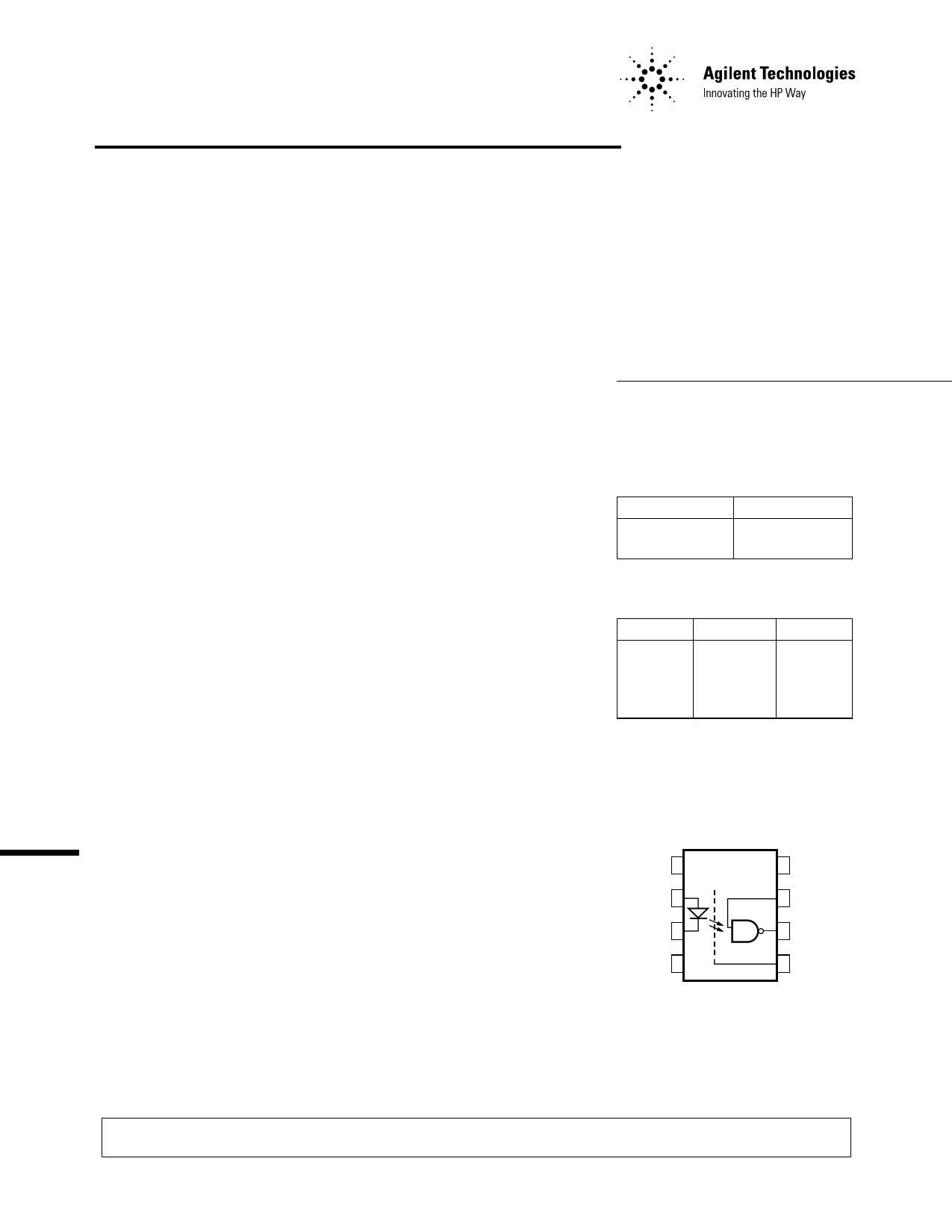
Functional Diagram
Multiple Channel Devices
Available
VCC
VE
VOUT
GND
The connection of a 0.1 µF bypass capacitor between VCC and GND is recommended.
CAUTION: It is advised that normal static precautions be taken in handling and assembly of this component to
prevent damage and/or degradation which may be induced by ESD.
1 page 
5
Hermetic Optocoupler Options
Option
100
Description
Surface mountable hermetic optocoupler with leads trimmed for butt joint assembly. This
option is available on commercial and hi-rel product in 8 and 16 pin DIP (see drawings below
for details).
4.32 (0.170)
MAX.
0.51 (0.020)
MIN.
2.29 (0.090)
2.79 (0.110)
1.14 (0.045)
1.40 (0.055)
0.51 (0.020)
MAX.
4.32 (0.170)
MAX.
0.51 (0.020)
MIN.
2.29 (0.090)
2.79 (0.110)
1.14 (0.045)
1.40 (0.055)
0.51 (0.020)
MAX.
NOTE: DIMENSIONS IN MILLIMETERS (INCHES).
0.20 (0.008)
0.33 (0.013)
7.36 (0.290)
7.87 (0.310)
200 Lead finish is solder dipped rather than gold plated. This option is available on commercial
and hi-rel product in 8 and 16 pin DIP. DSCC Drawing part numbers contain provisions for
lead finish. All leadless chip carrier devices are delivered with solder dipped terminals as a
standard feature.
300 Surface mountable hermetic optocoupler with leads cut and bent for gull wing assembly. This
option is available on commercial and hi-rel product in 8 and 16 pin DIP (see drawings below
for details). This option has solder dipped leads.
0.51 (0.020)
MIN.
2.29 (0.090)
2.79 (0.110)
4.57 (0.180)
MAX.
1.40 (0.055)
1.65 (0.065)
0.51 (0.020)
MAX.
4.57 (0.180)
MAX.
0.51 (0.020)
MIN.
2.29 (0.090)
2.79 (0.110)
1.40 (0.055)
1.65 (0.065)
0.51 (0.020)
MAX.
5° MAX.
NOTE: DIMENSIONS IN MILLIMETERS (INCHES).
0.20 (0.008)
0.33 (0.013)
9.65 (0.380)
9.91 (0.390)
4.57 (0.180)
MAX.
5 Page 
11
PULSE
GENERATOR
ZO = 50 Ω
tr = 5 ns
IF = 13 mA
D.U.T.
VCC
VE
VOUT
GND
OUTPUT VE
MONITORING
NODE
+5 V
0.01 µF
BYPASS
RL
OUTPUT VO
MONITORING
CL* NODE
* CL INCLUDES PROBE AND
STRAY WIRING CAPACITANCE.
Figure 9. Enable Propagation Delay
vs. Temperature.
Figure 8. Test Circuit for tEHL and tELH.
(EACH INPUT)
+–
VIN 5.3 V 200 Ω
(EACH OUTPUT)
D.U.T.*
VCC
VCC
+5.5 V
VOC
+5.5 V
0.01 µF
GND
200 Ω
(EACH OUTPUT)
CONDITIONS: IF = 20 mA
IO = 25 mA
TA = +125 °C
* ALL CHANNELS TESTED SIMULTANEOUSLY.
Figure 10. Operating Circuit for Burn-In and Steady State Life Tests.
11 Page | ||
| Páginas | Total 12 Páginas | |
| PDF Descargar | [ Datasheet HCPL-665x.PDF ] | |
Hoja de datos destacado
| Número de pieza | Descripción | Fabricantes |
| HCPL-665x | (HCPL-xxxx) Hermetically Sealed / High Speed / High CMR / Logic Gate Optocouplers | Hewlett-Packard |
| Número de pieza | Descripción | Fabricantes |
| SLA6805M | High Voltage 3 phase Motor Driver IC. |
Sanken |
| SDC1742 | 12- and 14-Bit Hybrid Synchro / Resolver-to-Digital Converters. |
Analog Devices |
|
DataSheet.es es una pagina web que funciona como un repositorio de manuales o hoja de datos de muchos de los productos más populares, |
| DataSheet.es | 2020 | Privacy Policy | Contacto | Buscar |